
Film component extraction apparatus

A technology for taking out devices and components, which is applied in the field of film component taking out devices, can solve problems such as taking out easily unstable sheets, and achieve the effects of reducing sliding, height positioning, and improving precision

Active Publication Date: 2010-02-24
FUJIFILM BUSINESS INNOVATION CORP
View PDF7 Cites 9 Cited by
  • Summary
  • Abstract
  • Description
  • Claims
  • Application Information

AI Technical Summary

Problems solved by technology

Therefore, in the technology described in Patent Document 1, when a sheet is adsorbed on the lower surface of the sheet taken out by floating, gas is injected or bent in the floating state to drop the lower sheet, and the subsequent Suction action to take out sheets that tend to be unstable in posture or falling position due to airflow when falling, deformation when bending, or force fluctuations

Method used


Image

  • Film component extraction apparatus
  • Film component extraction apparatus
  • Film component extraction apparatus

Examples


Embodiment 1

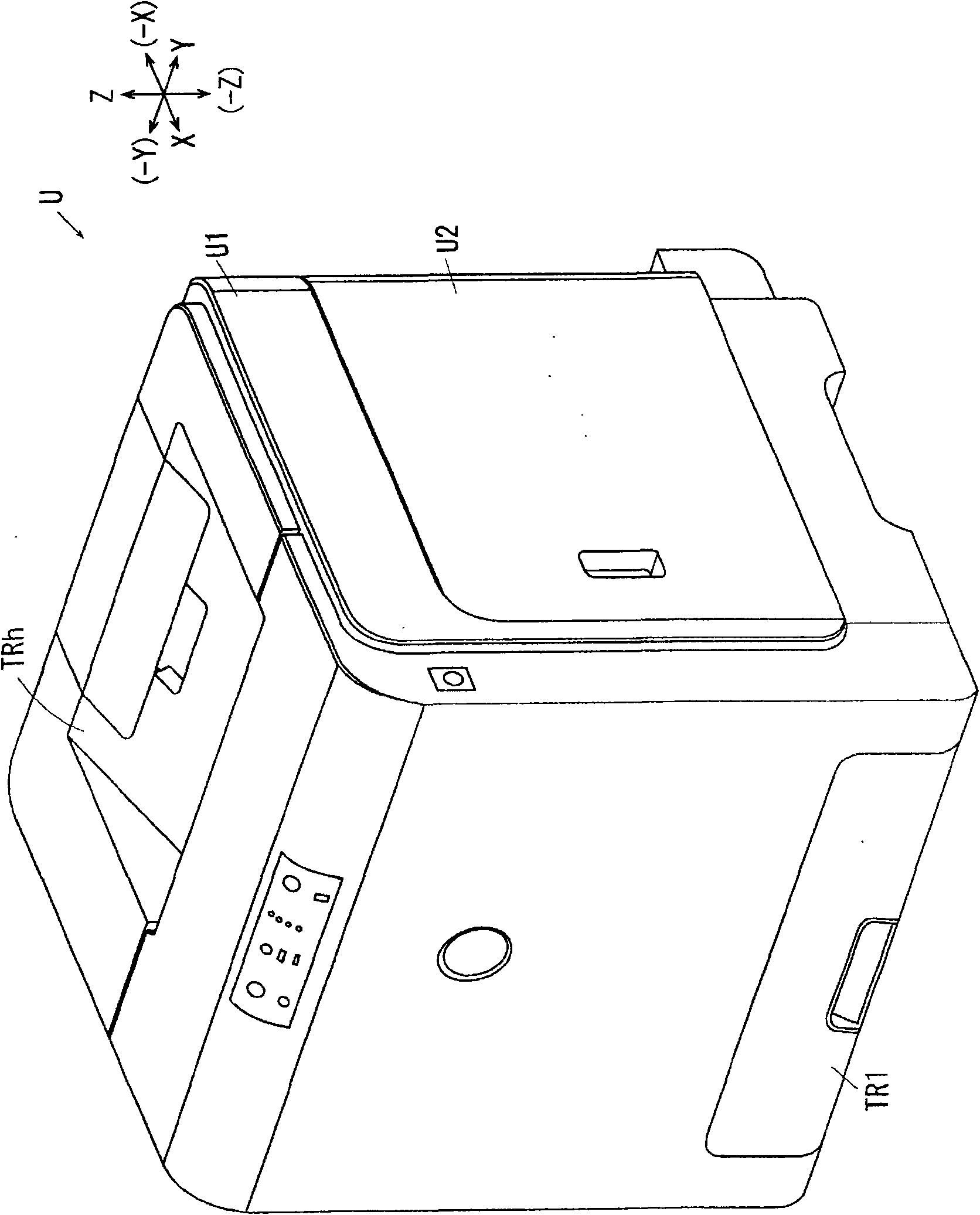
[0087] figure 1 It is a perspective view of a printer as an example of an image forming apparatus using a replacement container in which the film member separation device according to Example 1 of the present invention is used and assembled.

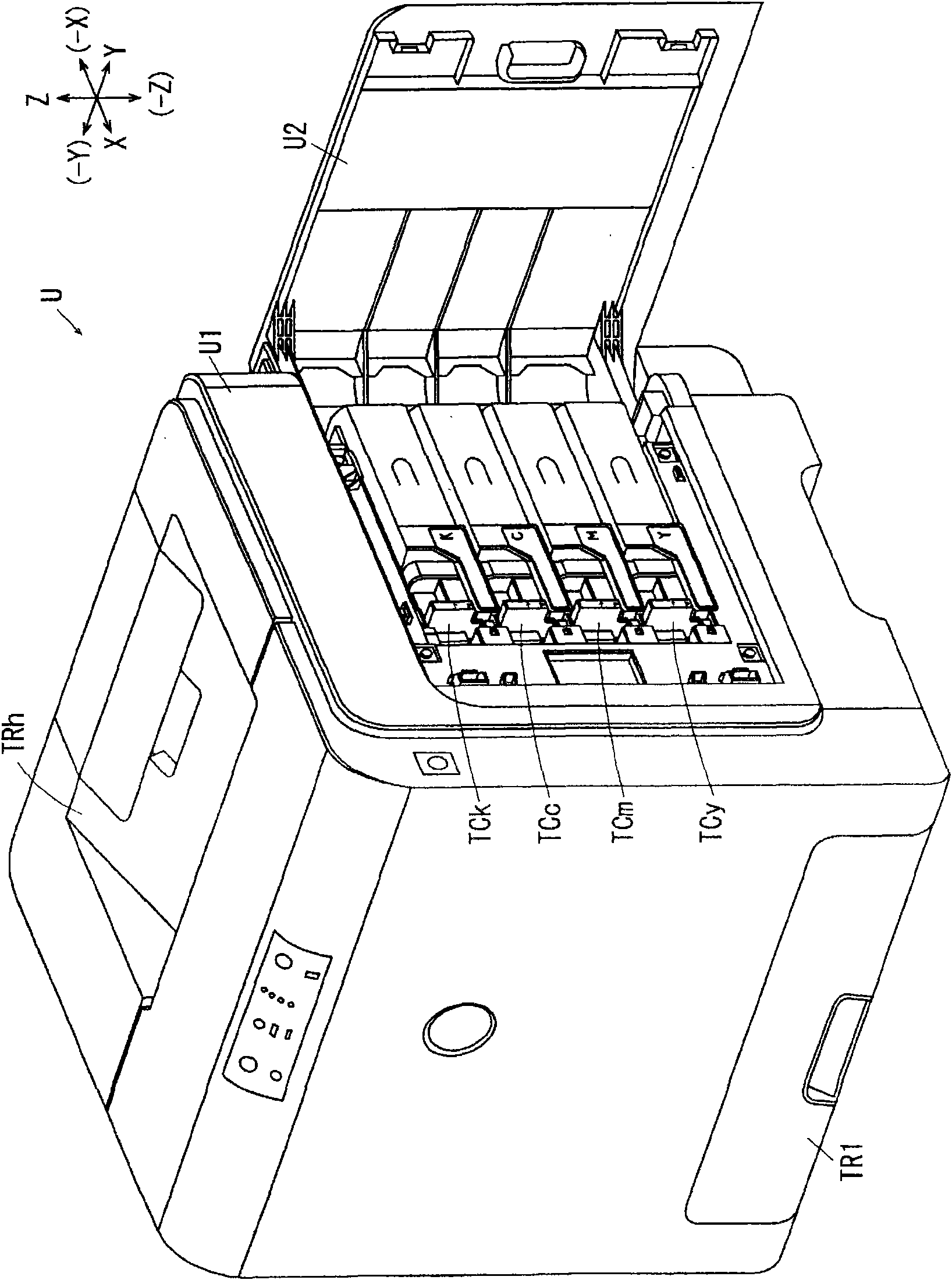
[0088] figure 2 for in figure 1 An explanatory diagram of the printer shown with the side cover open.

[0089] exist figure 1 , figure 2Among them, the full-color digital printer U of Embodiment 1 of the image forming apparatus of the present invention has an image forming apparatus main body U1. A paper feed tray TR1 as an example of a medium supply unit is supported on the lower portion of the image forming apparatus main body U1, and accommodates a medium on which an image is to be recorded on the front surface, and can be inserted and removed in the front-rear direction. On the upper surface of the image forming apparatus main body U1, there is formed a paper discharge tray TRh as an example of a medium discharge unit that ...

Embodiment 2

[0356] Figure 25 It is an explanatory diagram of the film taking-out device of Example 2, which is the same as that of Example 1. Figure 7 corresponding figure.

[0357] Figure 26 It is an explanatory drawing of the film storage box of the film apparatus of Example 2, and is a figure corresponding to FIG. 15 of Example 1. FIG.

[0358] Next, Embodiment 2 of the present invention will be described. In the description of Embodiment 2, constituent elements corresponding to constituent elements of Embodiment 1 are given the same reference numerals, and detailed description thereof will be omitted.

[0359] This second embodiment differs from the above-mentioned first embodiment in the following points, but is configured in the same manner as the first embodiment in other respects.

[0360] exist Figure 25 In the film take-out device FT of Example 2, compared with Example 1, the hoses 72' of the left blowing part 61e and the right blowing part 61f are connected to the gas s...


PUM

PropertyMeasurementUnit
Thicknessaaaaaaaaaa

Abstract

The invention relates to a film component extraction apparatus, which can separate the film components which is difficult to separate and forms incisions one by one to extract. The film component extraction apparatus (FT) has: a plurality of attraction portions (98), which is supported on the topside of the film component (8), can be contacted and separated, and forms an adsorption port (98a) on the front end, wherein the film component (8) is loaded in the housing portion (26), for form a plurality of incisions; a dividing direction mobile component (92), which enables each attraction portion (98) to move in the separated antisymmetric direction of the film component (8); and a contact separation direction mobile component (82), which enables the attraction portion to move in the contact separation direction relative to the loaded film component, attracts the film component loaded on uppermost surface on the attraction portion by inhaling gas, and enables the attraction portion to separate from the housing portion (26) to process extraction at a status that these attraction portions are closed to one another.

Description

technical field [0001] The invention relates to a device for taking out film parts. Background technique [0002] Techniques described in the following Patent Documents 1 to 3 are known as film member take-out devices that separate and take out film members such as so-called films and sheets one by one. [0003] In Japanese Unexamined Patent Publication No. 10-203660 as Patent Document 1, the following technology is described: first, keep the adsorbent (3a, 3b) in contact with the laminated soft sheets for a certain period of time, heat the sheets, and reduce the The adhesive force between the sheets makes it easy to peel off. Then, the soft sheets are adsorbed by the adsorbent (3a, 3b) to make them float up, and the gas is sprayed from the gas nozzle (5) to the interface between the sheets to separate them. Then, for the flakes that have not been separated even by blowing air, the adsorbent ( 3 a ) on one side is brought closer to the adsorbent ( 3 b ) on the other side to...

Claims


Application Information

Patent Timeline
IPC IPC(8): G03G15/00
CPCB65H1/266B65H3/0816B65H2301/42324
Inventor 丹友弥尾崎功古尾谷贤井上兼之
Owner FUJIFILM BUSINESS INNOVATION CORP
Learn More