Supercharge Your Innovation With Domain-Expert AI Agents!

Fan system and power reverse protection device thereof

A protection device and power supply technology, applied in the direction of emergency protection circuit devices, electrical components, etc., can solve the problems of difficult control, large coil volume, complex wiring, etc., and achieve the effect of low power consumption and small size

Active Publication Date: 2010-02-24
DELTA ELECTRONICS INC
View PDF1 Cites 10 Cited by
  • Summary
  • Abstract
  • Description
  • Claims
  • Application Information

AI Technical Summary

Problems solved by technology

However, the method of using a plurality of coils L1-LN to store energy to drive the NMOSFET 102 not only has too large volume of the coil, high cost of coil material, complicated circuit and difficult to control, but also utilizes the high capacitance of the capacitor 16 The way of voltage driving also consumes too much power

Method used


Image

  • Fan system and power reverse protection device thereof
  • Fan system and power reverse protection device thereof
  • Fan system and power reverse protection device thereof

Examples


no. 1 example

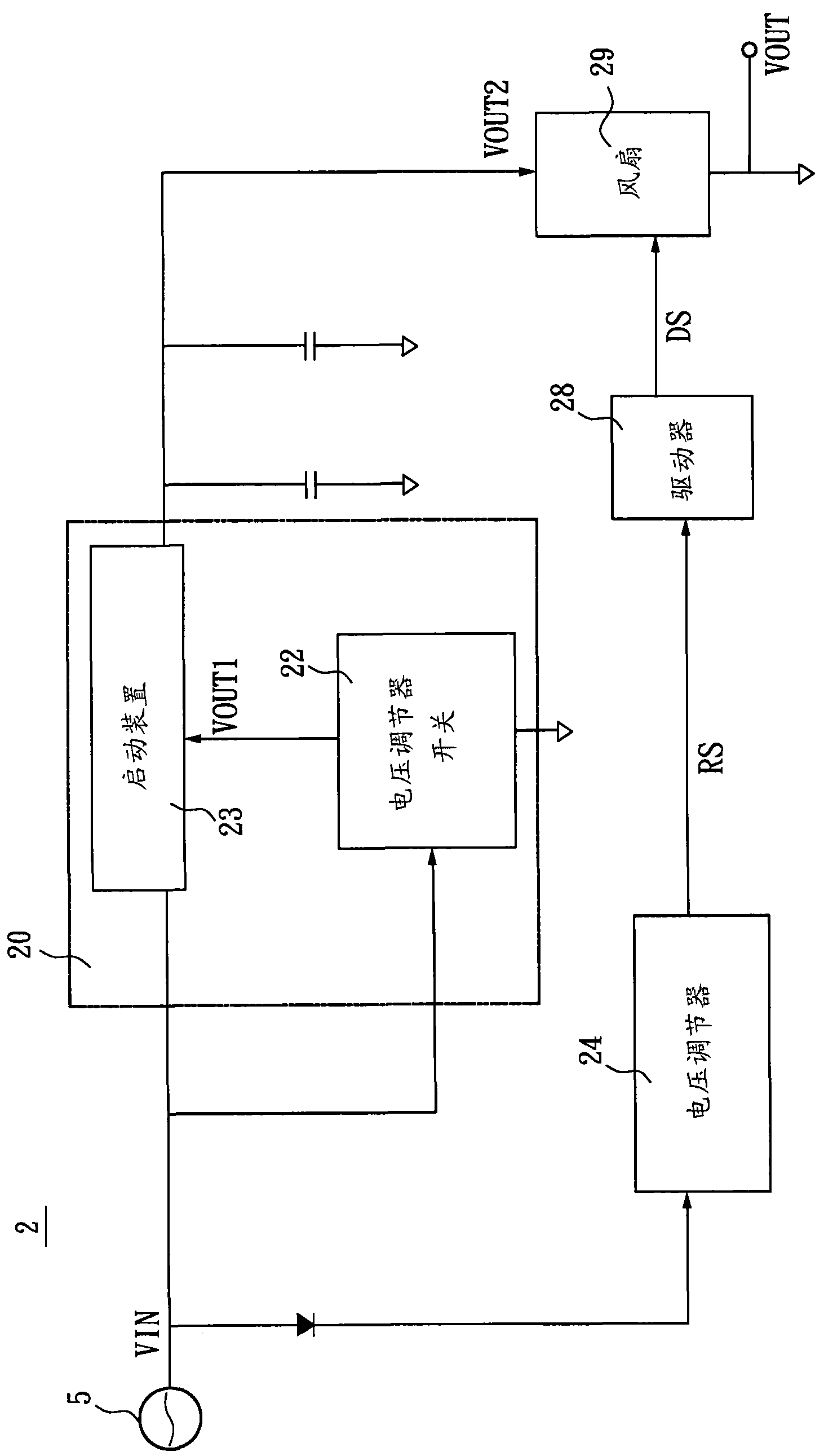
[0041] Please refer to figure 2 and image 3 , The fan system 2 of the first embodiment of the present invention includes a power reverse protection device 20 , a voltage regulator 24 , a driver 28 and a fan 29 . The voltage regulator 24 is electrically connected to the driver 28 and the power supply 5 respectively, the driver 28 is electrically connected to the voltage regulator 24 and the fan 29 respectively, and the power reverse protection device 20 is electrically connected to the power supply 5 and the fan 29 respectively.

[0042] The above power reverse protection device 20 mainly includes a voltage regulator switch 22 and a starting device 23; wherein the power reverse protection device 20 receives an input signal VIN from the power supply 5, and when the input signal VIN is a high potential signal, the voltage regulator switch 22 will is turned on and outputs the first output signal VOUT1. The starting device 23 is electrically connected to the voltage regulator s...

no. 2 example

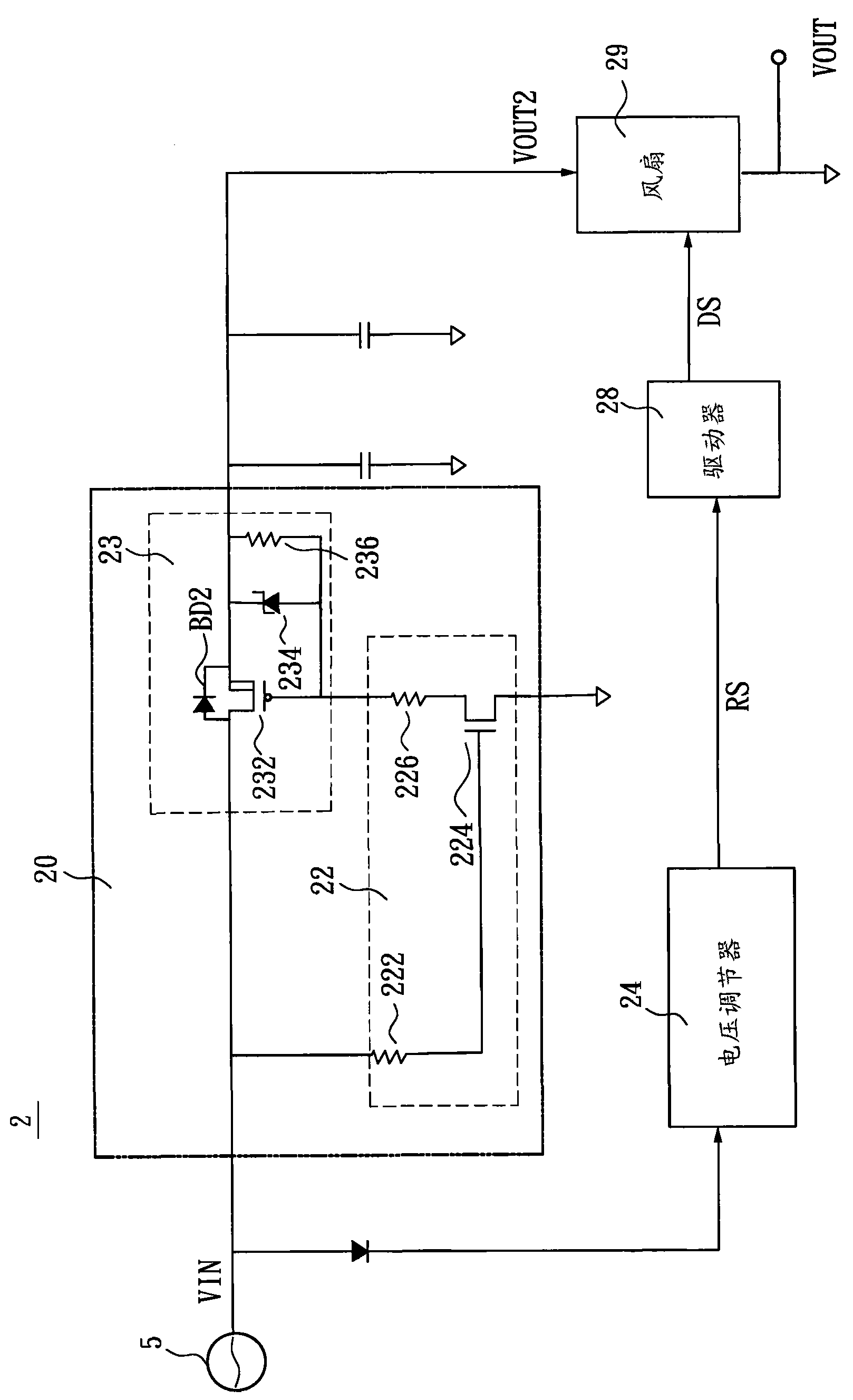
[0052] see Figure 4 and Figure 5 , The fan system 3 of the second embodiment of the present invention includes a power reverse protection device 30 , a voltage regulator 34 , a driver 38 and a fan 39 . The voltage regulator 34 is electrically connected to the power source 5 , the driver 38 and the power reverse protection device 30 respectively. The driver 38 is electrically connected to the voltage regulator 34 and the fan 39 respectively, and the power reverse protection device 30 is electrically connected to the power supply 5 , the voltage regulator 34 and the fan 39 respectively.

[0053] The main difference between this embodiment and the first embodiment is that the electrical connection of the voltage regulator switch 32 of the power reverse protection device 30 is changed from the power source 5 to the voltage regulator 34 .

[0054] The voltage regulator 34 includes a second resistor 342 , a second Zener diode 343 and a diode 344 . One end of the second resistor...


PUM


Abstract

The invention provides a fan system and a power reverse protection device thereof. The fan system is electrically connected with a power supply and comprises the power reverse protection device, a voltage regulator, a driver and a fan. The power reverse protection device is electrically connected with the power supply and comprises a voltage regulator switch and a starting device, wherein the voltage regulator switch receives an input signal from the power supply and determines a first output signal and outputs the first output signal; the starting device is electrically connected with the power supply and the voltage regulator switch, respectively receives the input signal and the first output signal, and determines whether to output a second output signal to the fan or not through the first output signal. The voltage regulator is electrically connected with the power supply, receives the input signal from the power supply, and outputs a regulation signal. The driver is electrically connected with the voltage regulator and is used for receiving the regulation signal and outputting a driving signal. The fan is respectively electrically connected with the driver and the power reverse protection device, respectively receives the driving signal and the second output signal, and operates according to the driving signal and the second output signal.

Description

technical field [0001] The invention relates to a fan system, in particular to a fan system which avoids reverse transmission of power supply signals and a power supply reverse protection device thereof. Background technique [0002] With the rapid development of science and technology, the higher the functional requirements for electronic equipment, the higher the number and integration of electronic components used, and the greater the power consumption demand of electronic equipment. Therefore, when the power consumption is large, Usually, a protection circuit is provided at the input end of the electronic device to protect the electronic device, and the performance of the protection circuit will directly affect the reliability and service life of the electronic device. [0003] At the input end of electronic equipment, it is a common structural setting to use the power reverse protection device to turn on the main power circuit in the electronic device and close the rema...

Claims


Application Information

Patent Timeline
Patent Type & Authority Applications(China)
IPC IPC(8): H02H11/00
Inventor 戴伟隆陈建桦
Owner DELTA ELECTRONICS INC
Features
  • R&D
  • Intellectual Property
  • Life Sciences
  • Materials
  • Tech Scout
  • Unparalleled Data Quality
  • Higher Quality Content
  • 60% Fewer Hallucinations
Learn More