Method for detecting the position of a closure element in a water distribution mechanism

A technology for closing elements and detection devices, applied in the field of position devices, can solve the problems of high cost and high complexity of dishwashers, and achieve the effects of reducing assembly work, simple structure, and fewer fault sources.

Active Publication Date: 2011-10-12
BSH BOSCH & SIEMENS HAUSGERAETE GMBH
View PDF8 Cites 0 Cited by
  • Summary
  • Abstract
  • Description
  • Claims
  • Application Information

AI Technical Summary

Problems solved by technology

A disadvantage of this is on the one hand the highly complex construction of the switching device, since both the outer wall and the additional elements in the switching device must ensure the guidance of the valve body
This overall results in higher costs for the manufacture of dishwashers

Method used


Image

  • Method for detecting the position of a closure element in a water distribution mechanism
  • Method for detecting the position of a closure element in a water distribution mechanism
  • Method for detecting the position of a closure element in a water distribution mechanism

Examples


Embodiment Construction

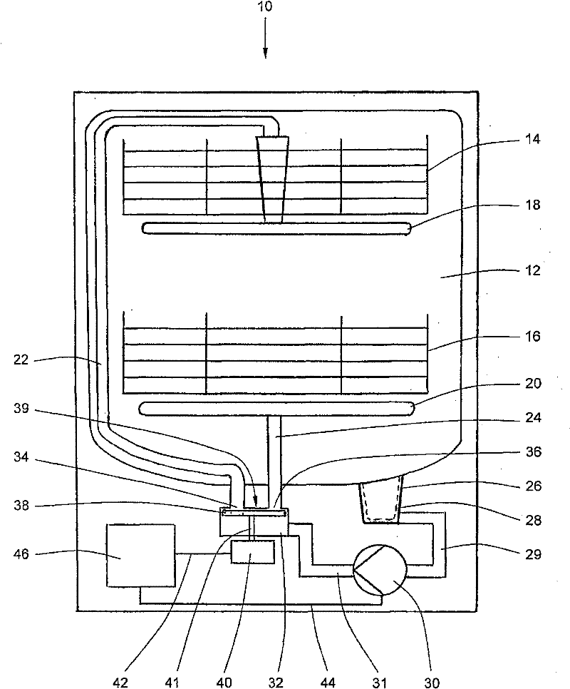
[0017] figure 1 is a schematic illustration of a dishwasher 10 having a washing container 12 within which an upper basket 14 and a lower basket 16 are arranged. An upper flushing system 18 is rotatably mounted below the upper basket 14, and a lower flushing system 20 is rotatably mounted below the lower basket 16, each in the form of a flushing arm. The upper flushing system 18 is supplied with flushing fluid via a supply line 22 and the lower flushing system is supplied with flushing fluid via a supply line 24 . Below the cleaning container 12 is a storage tank 26 which includes a filter inlet 28 which is connected to a circulation pump 30 via a fluid line 29 . Circulation pump 30 is connected to water splitter 32 via fluid line 31 . The water distributor comprises a cover surface 39 with two openings 34, 36, wherein the opening 34 is connected to the supply line 22 and the opening 36 is connected to the supply line 24.

[0018] A disk-shaped closing element 38 is rotatabl...


PUM


Abstract

The present invention relates to a method and device for detecting the position of a closure element (38) of a movement reversal device (32) in a dishwasher (10), wherein a predefined reference position of the closure element (38) is determined by means of a signal value of the recirculation pump (30).

Description

technical field [0001] The invention relates to a method for detecting the position of a closing element in a switching device of a dishwasher. The term "water diverter" can be used simultaneously with the term "conversion device". The function of the switching device is to distribute the rinsing fluid to the different rinsing systems and rinsing levels of the washing containers of the dishwasher. A circulation pump is used to deliver the flushing fluid. A drive device driven by the control device changes the position of the closing element. The invention also relates to a device for detecting the position of the closing element. Background technique [0002] A switching device of the type described is known from German patent publication DE 19857101 B4. The position of the closing element is detected via a rotational speed sensor which is located on the circulation pump upstream of the switching device. The sensor is connected to an electronic control unit which determ...

Claims


Application Information

Patent Timeline
Patent Type & Authority Patents(China)
IPC IPC(8): A47L15/42
CPCA47L15/0049A47L15/4221A47L15/4225A47L2401/08
Inventor M·罗森鲍尔D·塞梅拉德C·沃尔夫B·海泽勒A·奥布林格A·赖特尔
Owner BSH BOSCH & SIEMENS HAUSGERAETE GMBH
Why Eureka
Try Eureka