Gear wheel pump

A gear pump and gear technology, applied in the direction of pumps, pump components, rotary piston pumps, etc., can solve the problems of difficulty in disassembly and assembly, and achieve the effects of reliable transmission, easy disassembly, and high torque

Active Publication Date: 2010-02-24
OERLIKON TEXTILE GMBH & CO KG +1
View PDF3 Cites 7 Cited by
  • Summary
  • Abstract
  • Description
  • Claims
  • Application Information

AI Technical Summary

Problems solved by technology

But in known gear pumps, the drive shaft is connected to the gear via a press fit, which makes simple disassembly and assembly between drive shaft and gear difficult

Method used


Image

  • Gear wheel pump
  • Gear wheel pump
  • Gear wheel pump

Examples


Embodiment Construction

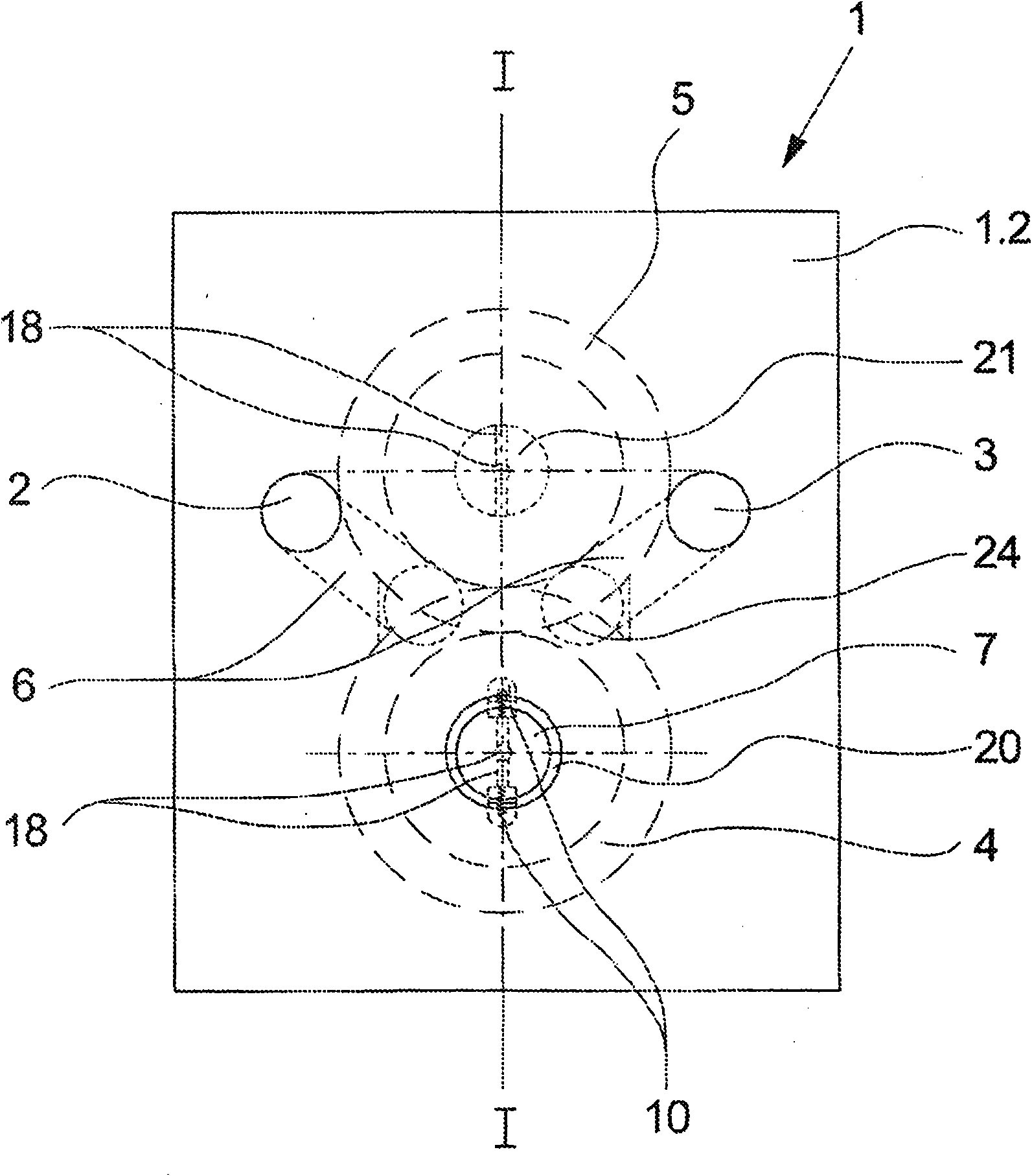
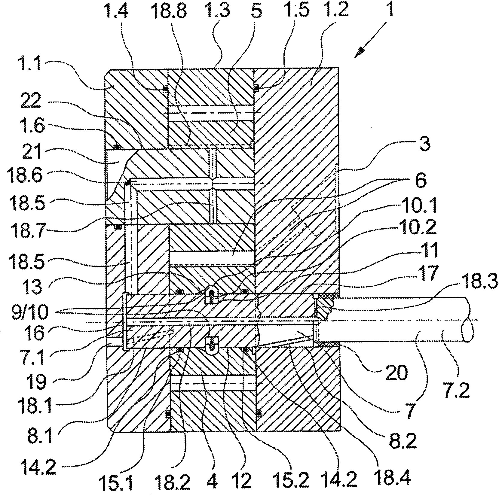
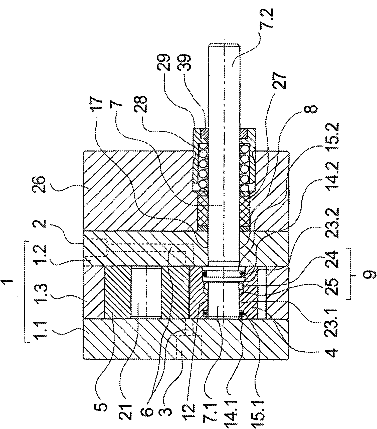
[0033] figure 1 and figure 2A first embodiment of the gear pump of the present invention is shown. figure 1 A front view of the gear pump is shown here, while figure 2 A cross-sectional view of the gear pump is shown. In this regard, the following description applies to both figures, where no particular emphasis is made on one of the figures.

[0034] The gear pump has a pump housing 1 which is multi-part and has housing plates 1.1 and 1.2 and an intermediate plate 1.3 held between the housing plates 1.1 and 1.2. A sealing ring 1.4 and 1.5 is provided on the end faces of the housing plates 1.1 and 1.2, by means of which the gaps between the intermediate plate 1.3 and the housing plates 1.1 and 1.2 are sealed towards the outside.

[0035] The intermediate plate 1.3 has respective openings for the two intermeshing gear wheels 4 and 5. In the overlapping region of the gear wheels 4 and 5, a delivery channel system 6 is formed in the housing parts, which is connected with a...


PUM


Abstract

The invention relates to a gear wheel pump with two meshing gear wheels which are rotatably mounted within a pump housing by means of a driven driveshaft and a crankshaft journal and which form a pumping channel system between a pump inlet and a pump outlet. Several gaps are formed between the pump housing, the gear wheels, the driveshaft, and the crankshaft journal. One of the gaps between the driveshaft and one of the gear wheels contains means for the rotationally fixed connection of the driveshaft to the gear wheel. In order to prevent leakages penetrating to the connecting means, according to the invention the gap between the driveshaft and the gear wheel is sealed, with respect to the front faces of the gear wheel, by means of a sealant.

Description

technical field [0001] The invention relates to a gear pump for conveying paints according to the preamble of claim 1 . Background technique [0002] A gear pump of this type is known from DE 10 2005 016 670 A1. The known gear pump has two meshing gears which are rotatably mounted in a pump housing via a drive shaft and a bearing journal. Together with a pump inlet and a pump outlet, the gears form a system of conveying channels in the pump housing for conveying a color paint in liquid or powder form. In order to prevent paint residues from flowing out of the delivery channel system via the gaps formed between the pump housing and the gear wheels and being distributed in the pump housing via the gaps, seals are provided between the end faces of the gear wheels and the pump housing. Furthermore, a system of flushing channels is formed in the pump housing in order to flush out possible color residues from the gaps between the pump housing, gear wheels, drive shaft and bearin...

Claims


Application Information

Patent Timeline
Patent Type & Authority Applications(China)
IPC IPC(8): F04C2/18F04C2/08F04C13/00F04C15/00
CPCF04C2/18F04C13/005F04C15/0038F04C2/086F04C2/08F04C13/00F04C15/00
Inventor A·汤姆齐克U·黑尔宾D·维茨勒M·鲍曼F·赫勒M·施蒂格勒H·马丁T·阿佩尔
Owner OERLIKON TEXTILE GMBH & CO KG
Why Eureka
Try Eureka