Supercharge Your Innovation With Domain-Expert AI Agents!

Refrigeration device

A refrigeration device and refrigerant technology, which is applied in the direction of refrigerators, refrigeration components, refrigeration and liquefaction, etc., can solve the problems that the capacity will not be fully utilized, and the flow rate of refrigerant refrigerant is insufficient.

Active Publication Date: 2010-02-24
DAIKIN IND LTD
View PDF1 Cites 26 Cited by
  • Summary
  • Abstract
  • Description
  • Claims
  • Application Information

AI Technical Summary

Problems solved by technology

Moreover, if there are multiple utilization units when the pressure difference between the inlet and outlet of the utilization side circuit is small, the refrigerant flow rate in the utilization units at a height where the refrigerant is relatively difficult to flow may not be sufficient, and the utilization Possibility that the capacity of the crew will not be fully utilized

Method used


Image

  • Refrigeration device
  • Refrigeration device
  • Refrigeration device

Examples


no. 1 approach

A first embodiment of the present invention will be described. This first embodiment is an air conditioner 20 constituted by a refrigeration device according to the present invention. The air conditioner 20 is configured to be selectable between cooling operation (cooling operation) and heating operation (heating operation).

[0055] (The overall structure of the air conditioner)

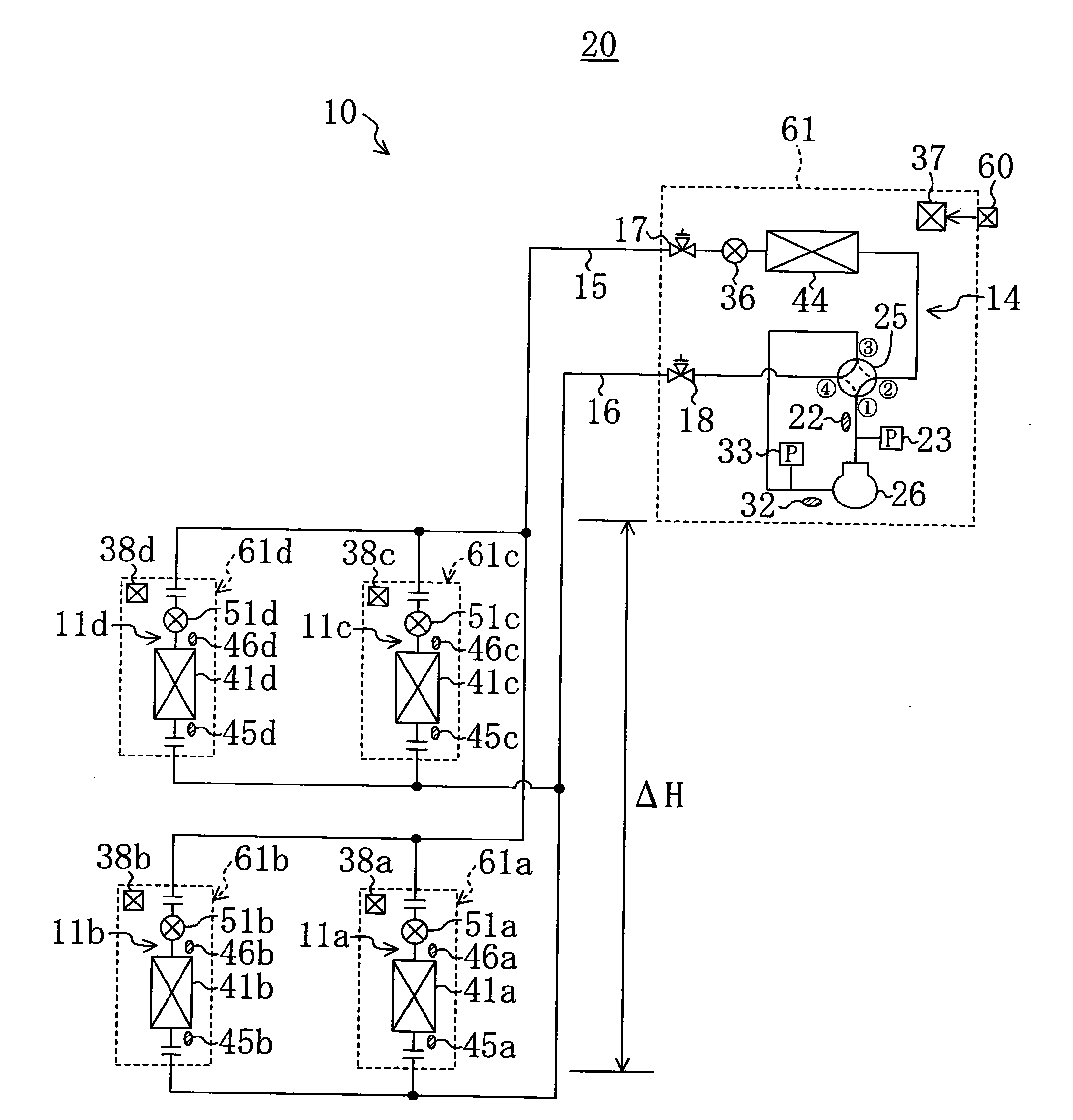
like figure 1 As shown, the air conditioner 20 in the first embodiment includes one outdoor unit 64 and four indoor units 61a, 61b, 61c, and 61d. The outdoor unit 64 which is a heat source unit is installed on the roof of the building. The first indoor unit 61 a , the second indoor unit 61 b ​​, the third indoor unit 61 c and the fourth indoor unit 61 d are all disposed below the outdoor unit 64 . The first indoor unit 61a and the second indoor unit 61b are installed on the same floor, and the third indoor unit 61c and the fourth indoor unit 61d are installed on the same floor. The first indoor u...

no. 2 approach

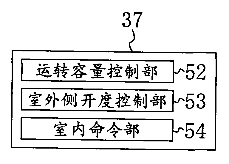
A second embodiment of the present invention will be described. Such as Figure 6 As shown, in the air conditioner 20 of the second embodiment, the outdoor control unit 37 is provided with an outdoor upper limit value setting unit 58 instead of the outdoor opening control unit 53 , and the outdoor control unit replaces the indoor command unit 54 . 37 is provided with an indoor upper limit value setting unit 59 . The outdoor upper limit setting unit 58 constitutes heat source side upper limit setting means. The indoor-side upper limit setting unit 59 constitutes use-side upper limit setting means.

[0109] Specifically, the outdoor upper limit setting unit 58 is configured to use the maximum height difference (ΔH) based on the height difference between the installation position of the outdoor unit 64 and the installation positions of the first and second indoor units 61a and 61b on the lowest floor. The upper limit value of the opening degree of the outdoor expansion valve 36...


PUM


Abstract

When a refrigeration device (20) performs cooling operation, the device is provided with heat source-side opening degree control means (53) that controls the degree of opening of a heat source-side expansion valve (36) so that the pressure of refrigerant flowing into a utilization-side expansion valve (51) during cooling operation is lower than or equal to a predetermined standard pressure value.When the refrigeration (20) performs heating operation, the device is provided with utilization-side opening degree control means (38, 54) that, when multiple utilization units (61) includes, during heating operation, an utilization unit (61) using a small flow amount of refrigerant that is less than an amount required for the refrigerant to exhibit its ability, reduces the degree of opening of the utilization-side expansion valves (51) of the utilization units (61) other than the utilization unit (61) using the small flow amount of the refrigerant.

Description

technical field [0001] The invention relates to a refrigeration device comprising a heat source unit and a utilization unit. Background technique [0002] So far, refrigerating devices including heat source units and utilization units are known. The heat source unit and the utilization unit are connected together through connecting pipes. An example of such a refrigeration device is disclosed in Patent Document 1. [0003] Specifically, Patent Document 1 discloses an air conditioner including an outdoor unit, a first indoor unit, and a second indoor unit. In this air conditioner, the outdoor unit is installed on a roof of a building, the first indoor unit is installed below the outdoor unit, and the second indoor unit is installed below the first indoor unit. An outdoor circuit is built in the outdoor unit, and an indoor circuit is built in each indoor unit. Each indoor circuit is connected in parallel to the outdoor circuit via the liquid side connecting pipe and the ga...

Claims


Application Information

Patent Timeline
IPC IPC(8): F25B1/00F25B6/02F25B13/00F25B49/02F25B39/00
CPCF25B13/00F25B2313/005F25B2600/2513F25B2500/19F25B2700/04F25B41/062F25B49/027F25B2313/0233F25B2600/19F25B2341/0662F25B2600/21F25B2313/02741F25B2500/01F25B41/39F25B41/35Y02B30/70F25B1/00F25B49/02F25B39/00
Inventor 河野聪松冈慎也
Owner DAIKIN IND LTD
Features
  • R&D
  • Intellectual Property
  • Life Sciences
  • Materials
  • Tech Scout
  • Unparalleled Data Quality
  • Higher Quality Content
  • 60% Fewer Hallucinations
Learn More