Intelligent gas leakage detecting apparatus

A technology for gas leakage and detection device, which can be applied to measurement devices, by detecting the appearance of fluid at the leakage point, and using liquid/vacuum for liquid tightness measurement, etc., can solve the leakage timeliness, supply pressure loss, installation trouble, etc. question

Inactive Publication Date: 2006-05-17
ZHEJIANG UNIV OF TECH
View PDF0 Cites 6 Cited by
  • Summary
  • Abstract
  • Description
  • Claims
  • Application Information

AI Technical Summary

Problems solved by technology

[0005] In order to overcome the deficiencies of the gas leakage detection device in the prior art that cannot perform real-time detection, find gas leakage is not timely, have pressure loss to the gas supply during measurement, poor sensitivity, and troublesome installation, the present invention provides a device that can automatically and real-time It is an intelligent gas leakage automatic detection device that detects gas leakage, can detect small changes in gas flow rate, has high sensitivity, can realize gas supply without pressure loss measurement, and is simple and convenient to install.

Method used


Image

  • Intelligent gas leakage detecting apparatus
  • Intelligent gas leakage detecting apparatus
  • Intelligent gas leakage detecting apparatus

Examples


Embodiment 1

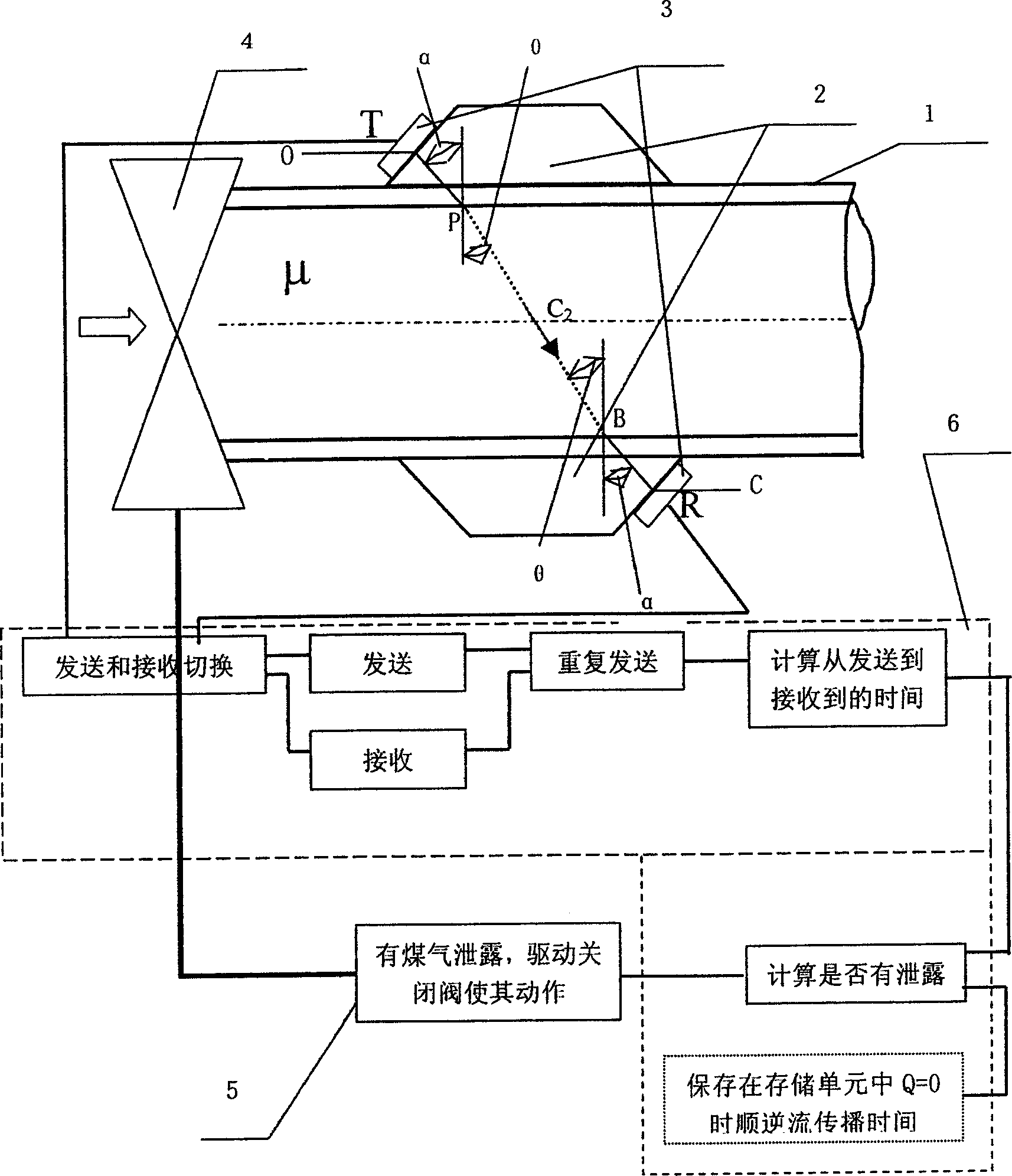
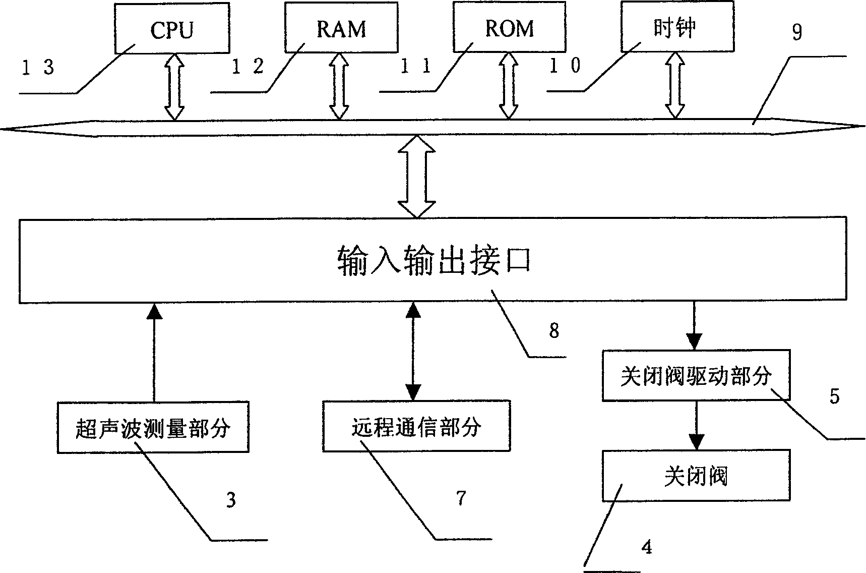
[0049] refer to figure 1 , figure 2 , image 3 , an intelligent gas leakage detection device, comprising a gas pipeline clamping part 2, a gas detection and control device installed in the clamping part 2, the gas detection and control device includes two ultrasonic transducers 3, a microprocessor 6, a closing valve 4, The output of the two ultrasonic transducers 3 is connected to the microprocessor 6, and the closing valve 4 is installed at the entrance of the gas pipeline 1; the two ultrasonic transducers 3 are installed on the opposite side of the clamping part 2, and the forward ultrasonic transducer The device is close to the user end of the gas pipeline, and the negative ultrasonic transducer is away from the user end of the gas pipeline; the microprocessor 6 includes a closing valve drive unit 5, a remote communication part 7, an input and output interface 8, an internal bus 9, and a clock 10 , ROM memory 11, RAM memory 12, computing unit CPU 13.

[0050] For the me...

Embodiment 2

[0079] refer to figure 1 , figure 2 , Figure 4 , the hardware configuration of this embodiment is the same as that of Embodiment 1.

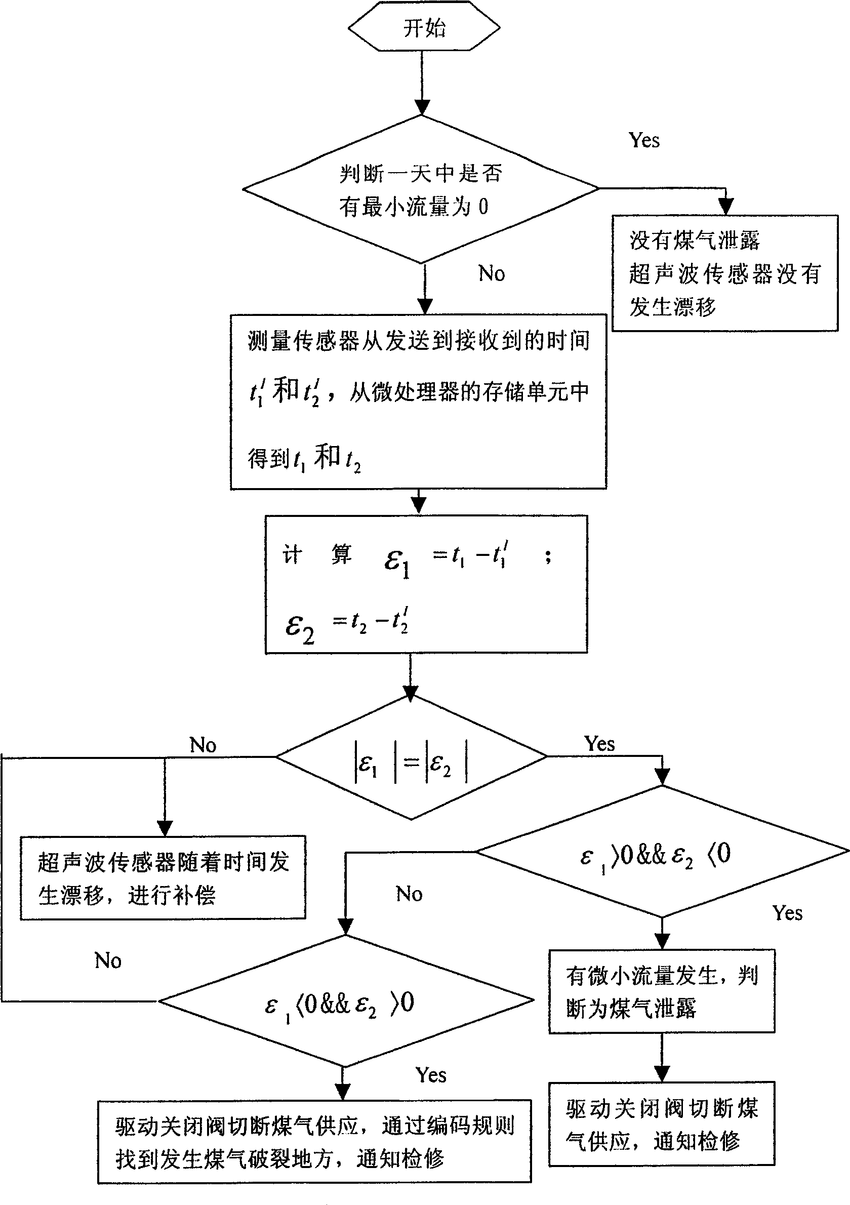
[0080] It is used to store the downstream propagation time t from the positive ultrasonic transducer to the negative ultrasonic transducer when the gas is in a static state (flow Q=0) every day of the year 1 d , The countercurrent propagation time t from the transmission of the negative ultrasonic transducer to the reception of the positive ultrasonic transducer 2 d The information storage part, the described information storage part is a part of ROM memory 11;

[0081] The microprocessor includes: during inspection and control, one of the two ultrasonic transducers can be selectively used as a transmitter and the other as a receiver for sending and receiving switching units; Downstream propagation time t from transmitting to the ultrasonic transducer to receiving by the negative ultrasonic transducer 1 l , The countercurrent propagati...


PUM


Abstract

The present invention relates to an intelligent gas leakage detection device. It includes gas pipeline mounting portion, gas pipeline control device mounted in the gas pipeline mounting portion, also includes two ultrasonic transducers, microprocessor and closing valve. Said invention also provides their connection mode. The described microprocessor includes transmitting and receiving switching unit, time metering unit, information storage portion, comparison analysis unit, closing valve driving unit and remote communication unit. Besides, said invention also provides its working principle and operation method.

Description

(1) Technical field [0001] The invention belongs to the application of ultrasonic detection technology, control technology and information technology in city gas safety protection, and is suitable for safe gas supply of city gas suppliers and safe gas use of every family using city pipeline gas. (2) Background technology [0002] In recent years, gas has entered thousands of households to guarantee the modern life of urban residents. But while citizens are enjoying the convenience brought by gas, some people swallow the bitter fruit of gas leakage from time to time. According to relevant departments, since gas entered a certain city in my country in 1993, more than a dozen or even dozens of people were killed in gas leakage accidents in the city almost every year. At present, the cities that introduced piped gas in the early stage of our country are facing a lot of gas safety maintenance work because the pipelines and rubber hoses have entered the aging stage. In short, wh...

Claims


Application Information

Patent Timeline
Patent Type & Authority Applications(China)
IPC IPC(8): G01M3/24G01N29/024G06F19/00
Inventor 汤一平
Owner ZHEJIANG UNIV OF TECH
Why Eureka
Try Eureka