Dehumidifier

A dehumidifier and dehumidification wheel technology, applied in the direction of separation method, heating method, lighting and heating equipment, etc., can solve the problem of uniform flow of non-condensing heat exchangers, etc., achieve the effect of reducing noise, simple operation process, and reducing the number of parts

Inactive Publication Date: 2010-03-03
LG ELECTRONICS INC
View PDF0 Cites 9 Cited by
  • Summary
  • Abstract
  • Description
  • Claims
  • Application Information

AI Technical Summary

Problems solved by technology

[0009] However, the problem with the existing condensing heat exchanger is that even if a plurality of heat exchange plates are used to increase the heat exchange area, the inside of the condensing heat exchanger cannot even flow

Method used


Image

  • Dehumidifier
  • Dehumidifier
  • Dehumidifier

Examples


Embodiment Construction

[0028] Preferred embodiments of the present invention that can specifically achieve the object of the present invention will be described below with reference to the accompanying drawings. When describing the embodiments of the present invention, the same names and the same reference numerals are used for the same structures, and additional descriptions thereof are omitted.

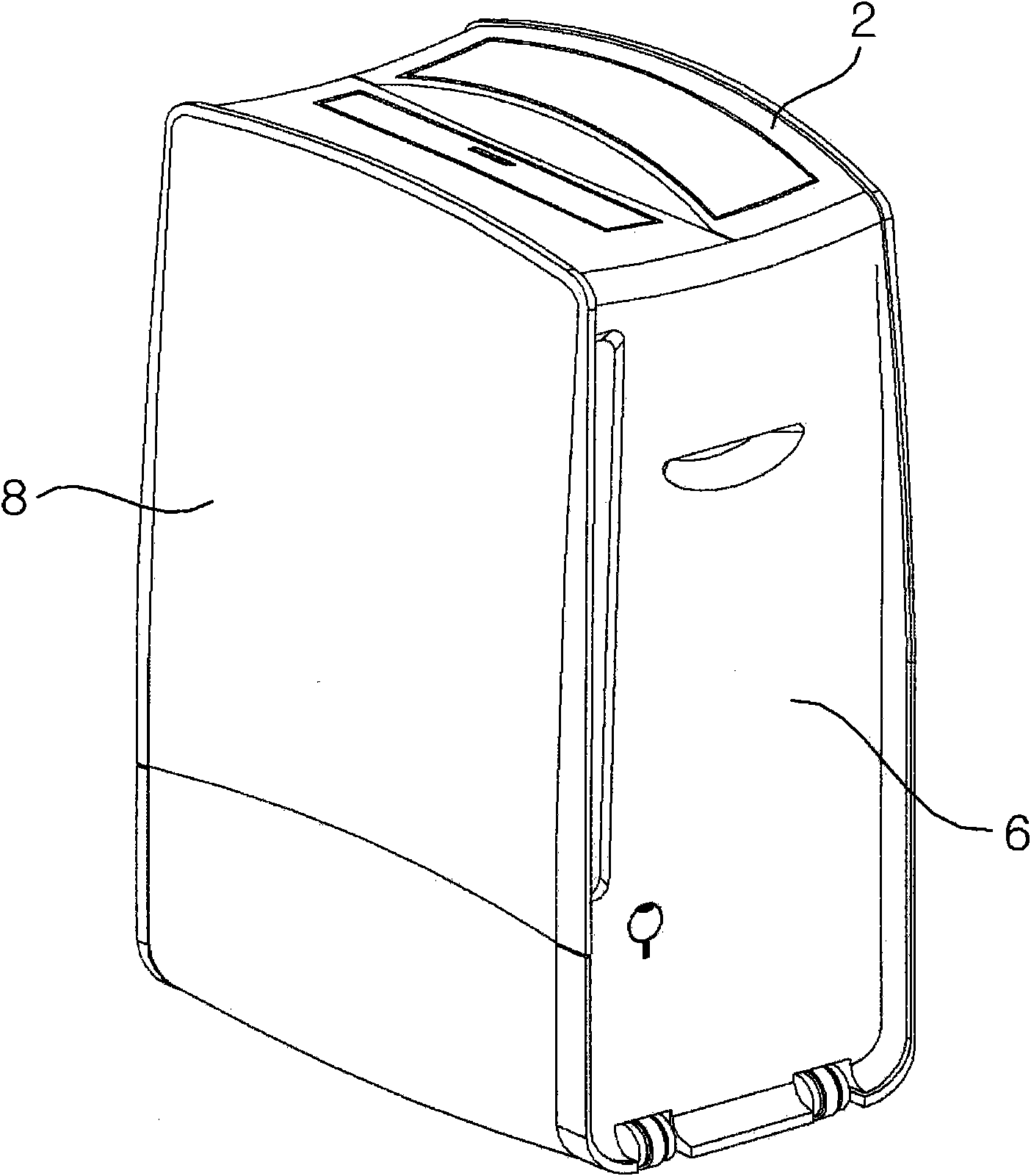
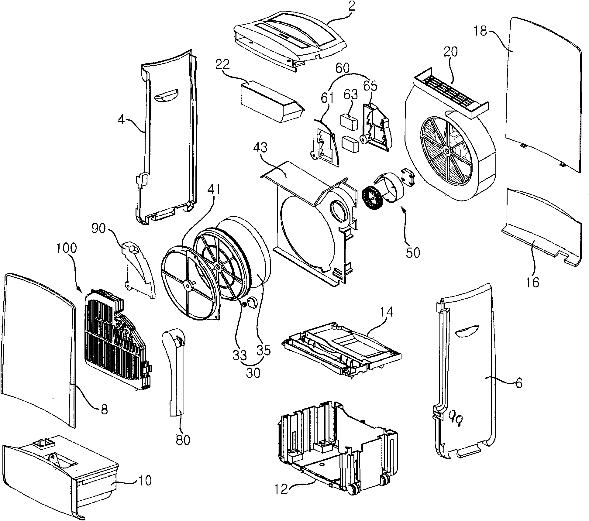
[0029] figure 1 is a perspective view of a dehumidifier according to an embodiment of the present invention, figure 2 for the above figure 1 An exploded perspective view of the main parts of the dehumidifier.

[0030] refer to figure 1 and figure 2 , to describe the overall configuration of the dehumidifier according to this embodiment.

[0031] According to the dehumidifier of this embodiment, after taking in indoor air and absorbing moisture, the dehumidified indoor air is discharged. Therefore, the main body is formed with: an air suction part for sucking in air; and an air discharge part for d...


PUM


Abstract

The present invention relates to a dehumidifier, including a dehumidification rotor partitioned into a dehumidification area, which is dehumidified while indoor air passes through the dehumidificationarea, and a reconditioning area, which is reconditioned while reconditioning air passes through the reconditioning area, a plurality of heat exchange plates configured to perform heat exchange of indoor air before the indoor air has passed through the dehumidification rotor and reconditioning air which has passed through the dehumidification rotor, and a reconditioning air distribution member placed between the reconditioning area of the dehumidification rotor and the heat exchange plates and configured to distribute the reconditioning air which has passed through the reconditioning area intothe plurality of heat exchange plates. Accordingly, the air which is able to be reconditioned in the heat exchange plates flows uniformly, the dehumidification capability of a dehumidifier can be improved and noise, generated when a dehumidifier is driven, can be reduced.

Description

technical field [0001] The present invention relates to a dehumidifier and, more particularly, to a system for distributing regeneration air to flow to a plurality of heat exchange plates so that the flow between the plurality of heat exchange plates is uniform, thereby improving heat exchange Condensing properties of the panels as well as dehumidifiers to reduce flow noise. Background technique [0002] Generally, dehumidifiers can be divided into dehumidifiers using refrigeration cycles and dehumidifiers using drying wheels according to their working methods. [0003] A dehumidifier using a refrigeration cycle requires a compressor, and there are problems such as compressor noise and securing a space for the compressor. Therefore, in recent years, dehumidifiers using a drying wheel have been widely used. [0004] The principle is that the drying wheel has the property of absorbing moisture in the air, and the indoor air is dehumidified through the drying wheel, and the hi...

Claims


Application Information

Patent Timeline
Patent Type & Authority Applications(China)
IPC IPC(8): B01D53/26F24F3/14
CPCF24F3/1423F24F3/14
Inventor 朴亨镐黄舜喆田一修
Owner LG ELECTRONICS INC
Why Eureka
Try Eureka