Disk workpiece processing method and structure

A processing method and workpiece technology, which is applied in the field of disc workpiece processing and structure, can solve the problems of long cycle time, long processing time, and low quality of parts, and achieve the effects of changing the stress state, improving processing accuracy, good drainage and chip removal Effect

Inactive Publication Date: 2010-03-03
郑勇阁
View PDF0 Cites 4 Cited by
  • Summary
  • Abstract
  • Description
  • Claims
  • Application Information

AI Technical Summary

Problems solved by technology

[0004] In addition, since the current automobile brake disc processing machine tools are mostly column-type upright lathes and inverted lathes, the processing is mainly done on one side first, and then on the reverse side. After two clampings, the parallelism accuracy of the two sides is not high, and the processing time is long. , the efficiency is low; there is also a brake disc lathe transformed from a horizontal lathe. Due to the weight of the workpiece and the vibration generated during processing, the quality of the processed parts is not high, the processing range is limited, and the surface quality is poor; the tools used are ordinary machine tools. , low feed speed and rotation speed, long cycle time and low efficiency; the complete set of processing equipment is composed of multiple machines, and the input cost is high

Method used


Image

  • Disk workpiece processing method and structure
  • Disk workpiece processing method and structure
  • Disk workpiece processing method and structure

Examples


Embodiment Construction

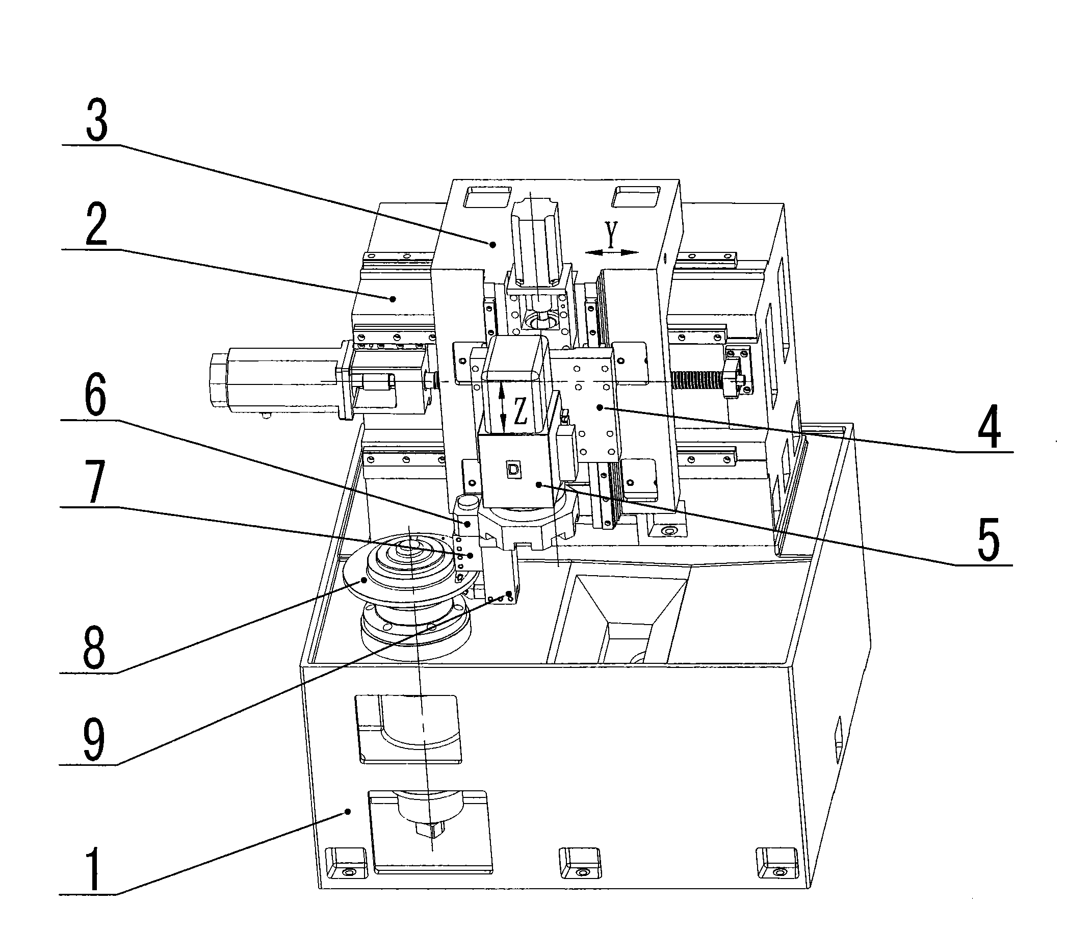
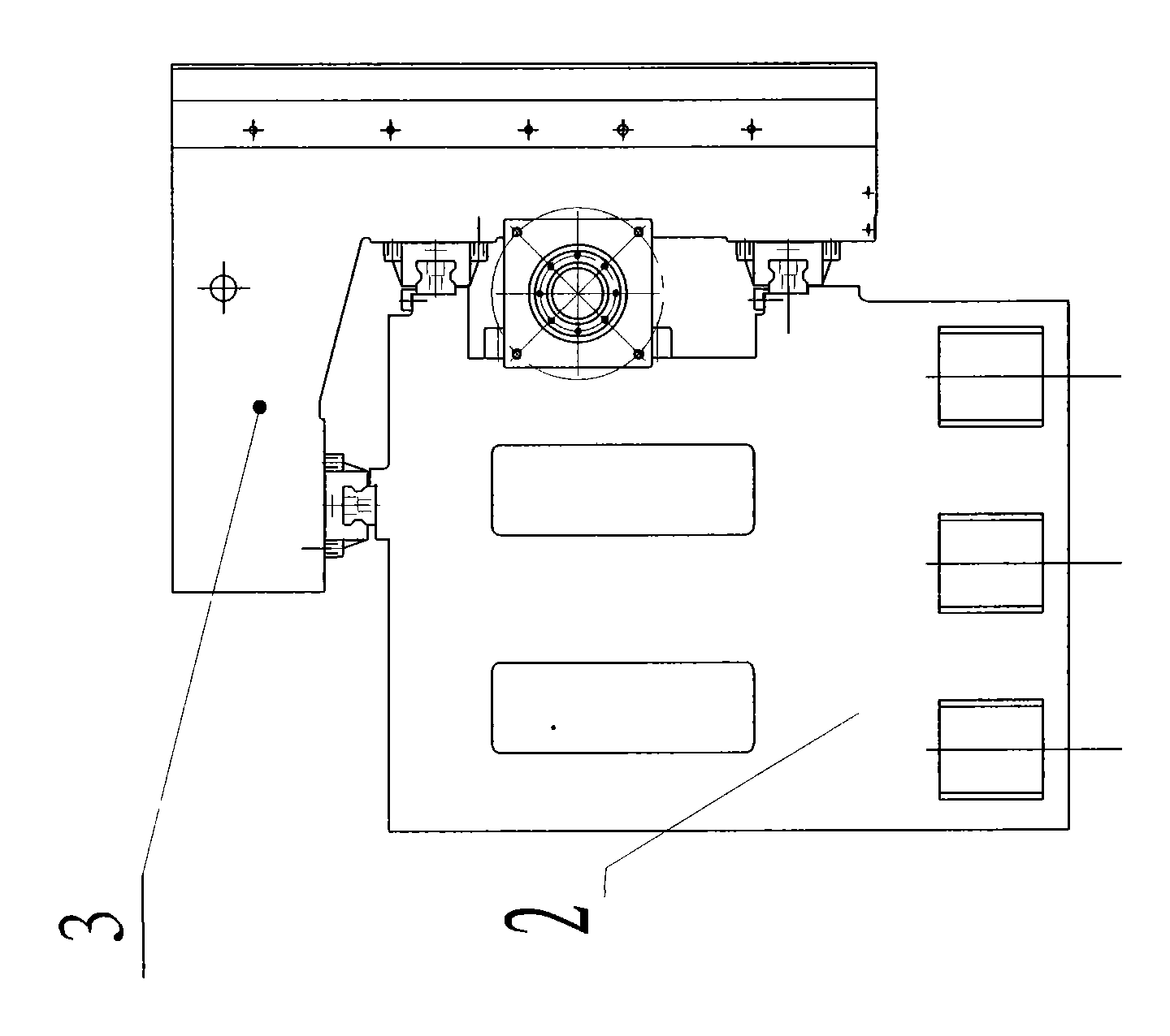
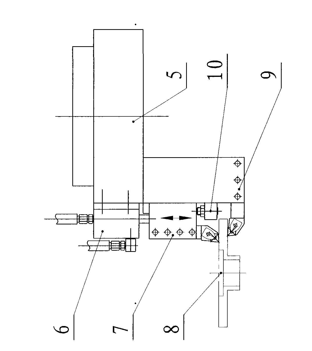
[0021] The method and structure of the present invention will be described in detail below in conjunction with the accompanying drawings. Such as figure 1 , image 3 As shown, the structure of the vertical lathe of the present invention includes a bed 1, a beam 2, a Y-axis curved plate saddle 3, a Z-axis saddle 4, and a turret 5; a tool rest 9 is arranged on the turret; There is a lower processing surface cutter 15, a positioning block 10 is arranged on the top of the tool rest, and a movable knife rest 7 is arranged above the positioning block 10; There is an upper processing surface cutter 14, and the top of the movable tool rest 7 is connected with the driving device 6. The driving device of the movable knife rest can adopt hydraulic mode, also can adopt the modes such as electric, mechanical, electromagnetic, as long as make the movable knife rest and positioning block can respectively guarantee to separate, close contact state all can reach the object of the present inv...


PUM


Abstract

The invention relates to a lathe structure, in particular to a vertical special numerical control lathe with a novel structure, high rigidity and high efficiency, which is used for processing disk workpieces, in particular brake disks of automobiles. The lathe comprises a lathe body, a beam, a Y-axis bent-plate sliding saddle, a Z-axis sliding saddle and a turret, and is characterized in that: theturret is provided with a tool rest; a lower processing surface tool is arranged under the tool rest; a positioning block is arranged above the tool rest; a movable tool rest is arranged above the positioning block, and can slide along the tool rest; an upper processing surface tool is arranged under the movable tool rest; and the upper part of the movable tool rest is connected with a driving device. The lathe has the advantages that: 1, the lathe can process two sides simultaneously to improve processing accuracy and production efficiency; 2, a three guide rail mode is adopted, so the lathemeets the condition of applying an PCBN tool; and 3, the lathe body adopts a completely inclined surface to achieve the aims of better draining water and removing chips.

Description

technical field [0001] The invention relates to a processing method and structure of disc-type workpieces, in particular to a high-rigidity and high-efficiency vertical special-purpose numerical control lathe of a new structure, which is used for processing disc-type workpieces, especially the processing of automobile brake discs. Background technique [0002] Due to economical and environmental reasons, dry machining has become a key research topic in the field of machine manufacturing in recent years. Cubic boron nitride CBN (Cubic Boron Nitride) was first synthesized by General Electric (GE) in the 1950s under high temperature and high pressure conditions. Its hardness is second only to diamond and much higher than other materials. Therefore, It and diamond are collectively referred to as superhard materials. [0003] CBN has high hardness, chemical inertness and thermal stability at high temperature, so it is widely used in grinding as abrasive CBN grinding wheel. Beca...

Claims


Application Information

Patent Timeline
Patent Type & Authority Applications(China)
IPC IPC(8): B23B1/00B23B21/00B23B17/00
Inventor 郑勇阁
Owner 郑勇阁
Why Eureka
Try Eureka