
Boring-milling machine

A boring and milling machine and boring shaft technology, which is applied in the field of boring and milling machines, can solve the problems of easy equipment failure, easy damage of transmission mechanism, limited adjustment range, etc., and achieve the effect of improving reliability, reducing failure and stabilizing output power

Inactive Publication Date: 2010-03-03
简东灿
View PDF0 Cites 7 Cited by
  • Summary
  • Abstract
  • Description
  • Claims
  • Application Information

AI Technical Summary

Problems solved by technology

Due to the large number of structural parts required by the transmission system, the installation location also has high coordination requirements. Every time the speed is changed, the gears need to be separated and combined, and the equipment is prone to failure.
[0003] In order to process some special parts, special equipment with multiple processing stations has also appeared. Among these special equipment, there are also two types of equipment that combine milling and boring. Milling and boring are performed by two machines of the same machine tool. The complete set of power and transmission system is independent of each other. The power and transmission mechanism are used respectively. In order to obtain different speeds, multiple sets of speed change gears are used to achieve the goal. Such equipment is just a simple superposition of two machine tools, the milling machine and the boring machine. The transmission system is still Complicated, the speed change mechanism will still be easily damaged when the speed is changed, and the equipment cost is high
[0004] Existing machine tools use servo motors as the power source, and the speed adjustment of the servo motor can be used to adjust the final number of revolutions of the machining axis, but the change in the number of revolutions of the servo motor will affect its actual output power, so the adjustment range is limited

Method used


Image

  • Boring-milling machine
  • Boring-milling machine

Examples


no. 1 approach

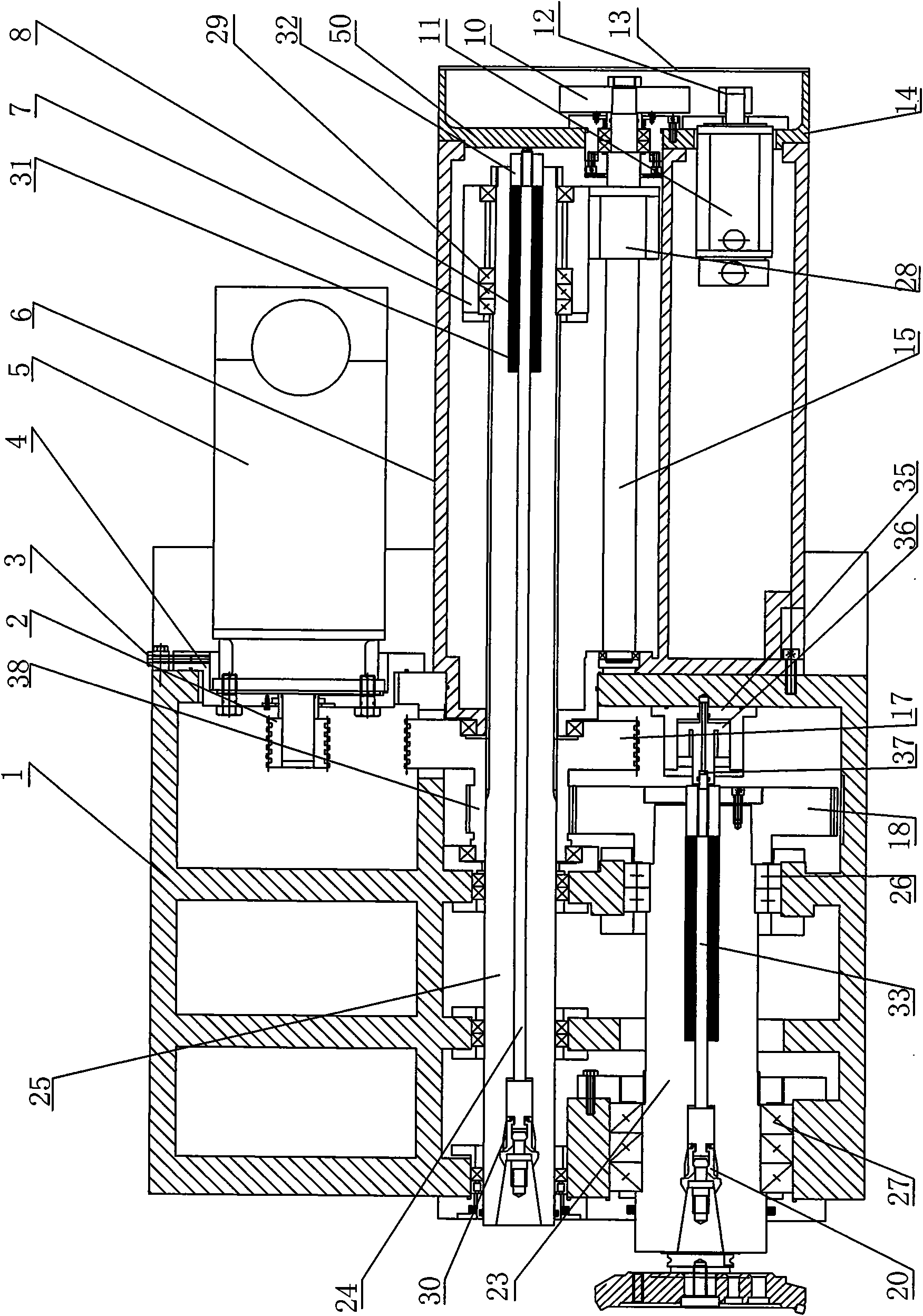
[0023] Such as figure 1 The shown boring and milling machine comprises a spindle box 1, a servo motor 5, a boring shaft 25, a milling shaft 23 and a tail box 6; Seat 14, tail box rear cover plate 13 is installed on the upper end of tail box rear seat 14, like this, can guarantee the safety of using lathe, and can prevent in the tail box 6 and the main shaft box 1 that water, dust enter and affect the use of lathe; A servo motor base 4 is installed on the spindle box 1, a servo motor 5 is installed on the servo motor base 4, and a pre-tightening adjustment screw 3 is provided between the spindle box 1 and the servo motor base 4 for adjusting the position of the servo motor 5; The boring shaft 25 is slidably installed in the headstock 1, and the end of the boring shaft 25 away from the boring tool is extended into the tail box 6; the milling shaft 23 is installed in the headstock through a non-axial locating bearing and a locating bearing 1. In this embodiment, the non-axial po...

no. 2 approach

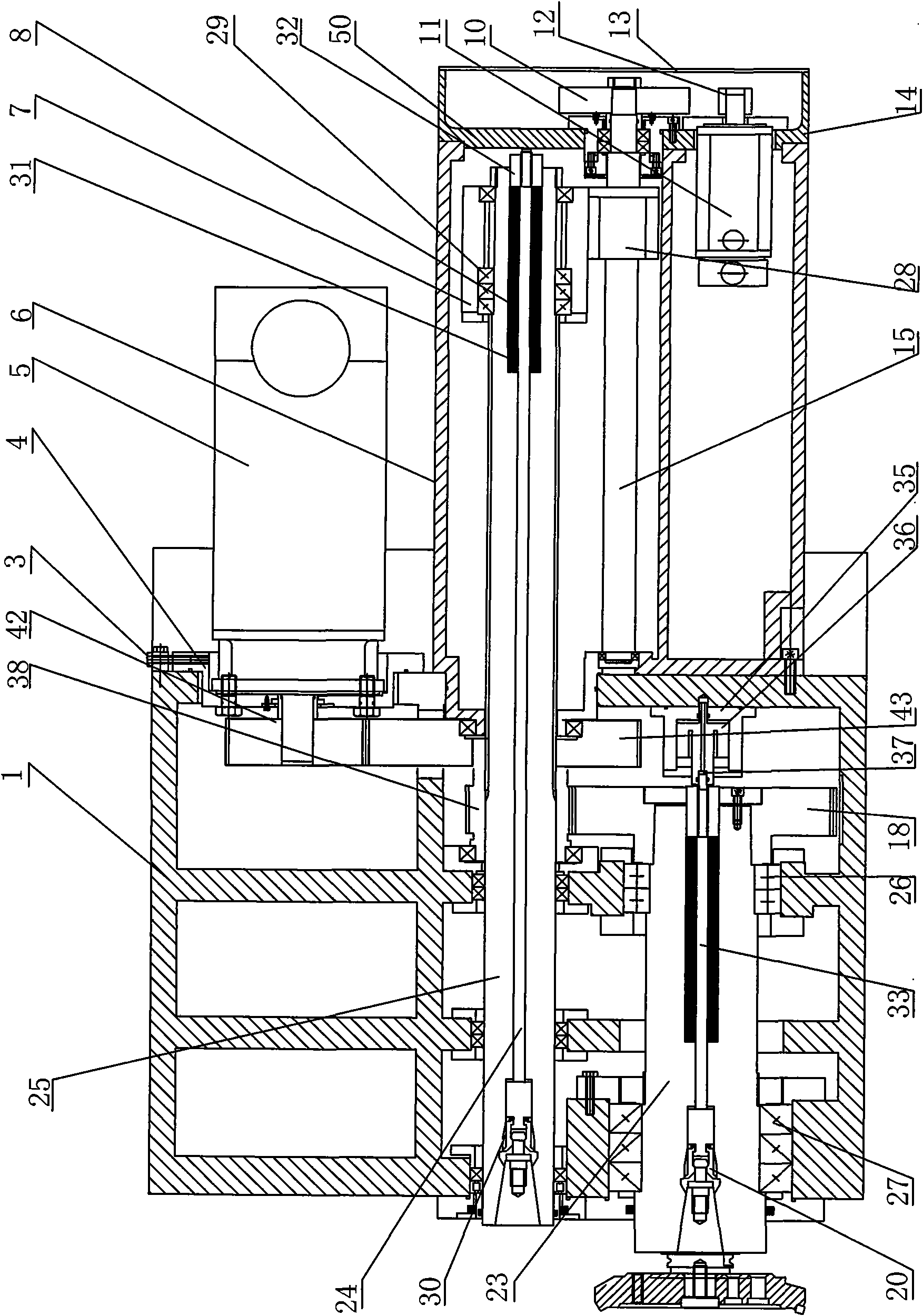
[0034] Such as figure 2The shown boring and milling machine comprises a spindle box 1, a servo motor 5, a boring shaft 25, a milling shaft 23 and a tail box 6; Seat 14, tail box rear cover plate 13 is installed on the upper end of tail box rear seat 14, like this, can guarantee the safety of using lathe, and can prevent in the tail box 6 and the main shaft box 1 that water, dust enter and affect the use of lathe; The spindle box 1 is equipped with a servo motor base 4, and the servo motor 5 is installed on the servo motor base 4; the boring shaft 25 is slidably installed in the spindle box 1, and the boring shaft 25 extends into the tail box away from the end where the boring tool is installed 6; the milling shaft 23 is installed in the headstock 1 through a non-axial locating bearing and a locating bearing. In this embodiment, the non-axial locating bearing is a double-row cylindrical roller bearing 26, and the axial locating bearing is Angular contact bearing 27, double-ro...


PUM


Abstract

The invention discloses a boring-milling machine, comprising a spindle box, a boring shaft, a milling shaft and a servo motor. The power of the servo motor is transmitted to the boring shaft and the milling shaft by a main transmission system. The boring shaft is a middle transmission shaft between the milling shaft and the servo motor. The boring-milling machine can lower the cost, simplify the transmission system, ensure low damage possibility of the transmission system, prolong the service life of the machine tool, simultaneously optimize the motor power and save the energy.

Description

technical field [0001] The invention relates to a boring and milling machine. Background technique [0002] Mechanical equipment occupies a dominant position in various processing, especially lathes, milling machines, boring machines, planers, grinding machines and other equipment. Now, in order to automate processing, improve processing speed and precision, CNC machine tools have appeared; among the above mechanical equipment, milling machines It is used to process flat parts. The boring machine mainly finishes the holes. The processing of planes and holes is often encountered in mechanical processing. For these two types, the traditional processing methods are usually processed on different machine tools. That is, the plane is processed on a milling machine, and the precise hole is processed on a boring machine. In this way, two sets of equipment are needed, the cost is high, and the workpiece needs to be installed many times, and the processing accuracy is not high. In or...

Claims


Application Information

Patent Timeline
IPC IPC(8): B23B39/02B23B19/02B23B29/00B23C5/26B23Q5/10
Inventor 简东灿
Owner 简东灿
Learn More