Method for saving energy and producing more propylene in absorption-stabilization system by catalytic cracking

An absorption stabilization system and catalytic cracking technology, applied in catalytic cracking, cracking, chemical industry, etc., can solve problems such as gasoline yield decline, liquefied gas loss, and device control and adjustment difficulties, and achieve the effect of reducing the total load

Active Publication Date: 2010-03-03
PETROCHINA CO LTD
View PDF0 Cites 28 Cited by
  • Summary
  • Abstract
  • Description
  • Claims
  • Application Information

AI Technical Summary

Problems solved by technology

The single-tower process mainly has the following disadvantages: the absorption and desorption processes are carried out in the same tower, and the mutual interference is relatively large; it is difficult to achieve a high absorption rate and desorption rate; it is difficult to control and adjust the device
[0006] The double-tower process overcomes the shortcomings of the above-mentioned single-tower process to a certain extent, but there are generally problems in the following aspects: (1) Excessive desorption of the desorption tower leads to a large amount of C3 and C4 components in the absorption tower and desorption tower cycle, increasing the energy consumption of the process
(2) Only raw crude gasoline and rich gas are separated into dry gas, liquefied gas, and stable gasoline products, making it difficult to adjust the olefin content in stable gasoline products
(3) The absorption effect of the absorption tower is not ideal, and the dry gas contains a large amount of liquefied gas components, resulting in the loss of liquefied gas
(4) The separation capacity of the stabilization tower is not enough, the high content of carbon five components in the liquefied gas makes the quality unqualified, and the gasoline yield decreases
(5) The content of C4 in stable gasoline products is high, resulting in unqualified gasoline vapor pressure

Method used


Image

  • Method for saving energy and producing more propylene in absorption-stabilization system by catalytic cracking
  • Method for saving energy and producing more propylene in absorption-stabilization system by catalytic cracking
  • Method for saving energy and producing more propylene in absorption-stabilization system by catalytic cracking

Examples


Embodiment 1

[0023] Example 1: Energy-saving and productive propylene process desorption tower T302 hot feed scheme

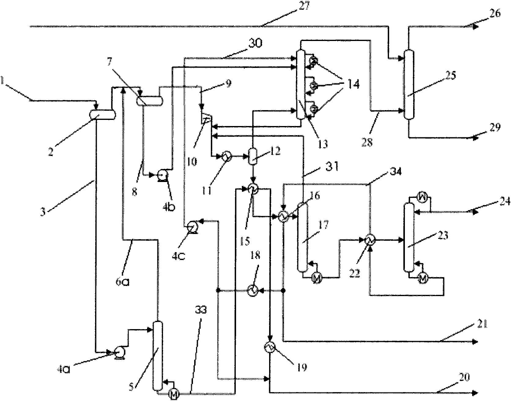
[0024] Taking an oil refinery with a catalytic processing capacity of 0.4Mt / a as an example for simulation, its rich gas flow rate is 8000kg / h, the flow rate of light gasoline is 7000kg / h, and the flow rate of heavy gasoline is 4000kg / h. The heavy gasoline separated by the heavy gasoline separator V201A enters the top of the absorption stabilization system after being pressurized and cooled, and the newly added desorption tower T305, the desorption tower T305 separates the heavy gasoline into the top desorption tower rich in C1~C4 components under low pressure operation. Stable gasoline with aspirated and low olefin content. The rich gas separated from the light gasoline separator V201B is pressurized, mixed with the saturated absorption oil at the bottom of the absorption tower T301 and the desorbed gas at the top of the desorption tower T302, cooled to 30°C-45°C, and then...

Embodiment 2

[0026] Example 2: Energy-saving and productive propylene process desorption tower T302 double-strand feeding scheme

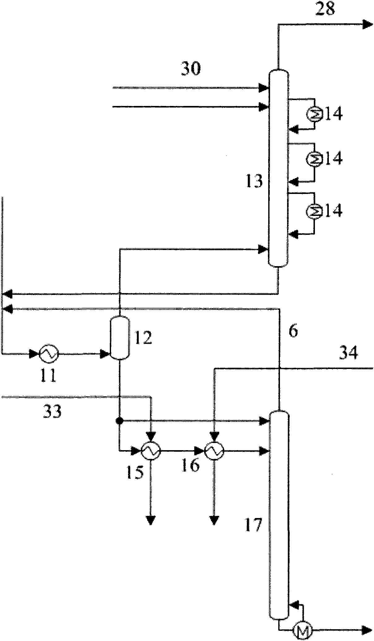
[0027] Divide the liquid phase of the vapor-liquid balance tank of the desorption tower T302 hot feed process into two streams, one as cold feed into the top of the desorption tower T302, and the other hot feed into the upper part of the desorption tower T302; for effective use and stability The heat of gasoline, the hot stream first passes through the heat exchanger E301 and the stable gasoline at the bottom of the desorption tower T305 to exchange heat to 35°C-50°C, and then heats up to 50°C-90°C after heat exchange through the heat exchanger E302. This example is the improvement of Example 1, except the above-mentioned improved part, all the other technological processes are the same as Example 1.

Embodiment 3

[0028] Example 3: Energy-saving and productive propylene process desorption tower T302 intermediate reboiler scheme

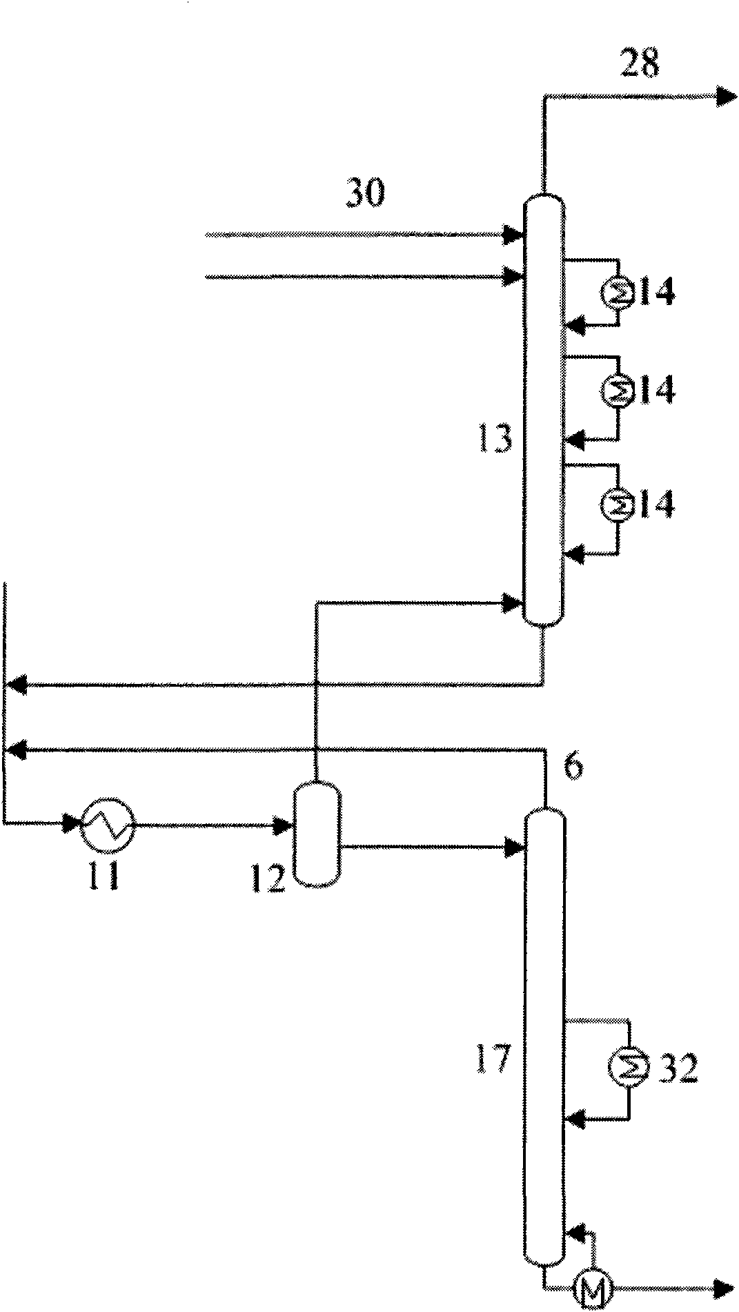
[0029] The heat exchanger E301 and the heat exchanger E302 in the hot feed process of the desorption tower T302 are canceled, and the liquid phase of the vapor-liquid balance tank directly enters the top of the desorption tower T302; and an intermediate reboiler (32) is set in the lower part of the desorption tower T302, Its return temperature is 70°C to 110°C. The heat for the intermediate reboiler comes from stabilizing gasoline. This example is the improvement of Example 1, except the above-mentioned improved part, all the other technological processes are the same as Example 1.

[0030] Under the same feed and product specifications, the treatment effects of Example 1, Example 2 and Example 3 are compared with the treatment effects of the conventional thermal feed process of the double-tower flow process. The comparison results of the four processes are as...


PUM


Abstract

The invention relates to a method for saving energy and producing more propylene in an absorption-stabilization system by catalytic cracking. A liquid phase of a vapor-liquid equilibrium tank exchanges heat with stable gasoline on the bottom of a desorber T305 through a heat exchanger E301, exchanges heat with stable gasoline on the bottom of a stabilization tower T304 through a heat exchanger E302, and then enters a desorber T302; deethanized gasoline on the bottom of the desorber T302 exchanges heat with the stable gasoline on the bottom of a stabilization tower T304 through a heat exchanger E305, and then enters the stabilization tower T304; the stable gasoline on the bottom of the stabilization tower T304 is cooled by the heat exchanger E305 and the heat exchanger E302, a part of the stable gasoline enters a reaction-regeneration system for recycling, the rest stable gasoline is cooled by a heat exchanger E303, and a part of the rest stable gasoline enters an absorption tower T301; and the stable gasoline on the bottom of the desorber T305 is subjected to two-stage cooling of the heat exchanger E301 and a heat exchanger E304, serves as a stable gasoline product and is discharged from the device. The thermal load is reduced by 15.8 to 17.7 percent; and the alkene content in the stable gasoline product is reduced by 34.3 percent.

Description

technical field [0001] The invention relates to a method for saving energy and producing more propylene in a catalytic cracking absorption stabilization system. Background technique [0002] The catalytic cracking unit is one of the main refining units. It is an important device for lightening heavy oil and producing liquefied gas, gasoline and diesel. The absorption stabilization device is a post-processing system in the catalytic cracking unit, which separates the crude gasoline and rich gas from the top of the catalytic fractionation tower into product liquefied gas and stable gasoline, and at the same time obtains dry gas as a by-product. In recent years, with the acceleration of gasoline quality upgrading, it is necessary to cut gasoline into two fractions, light and heavy, so that the heavy fraction can be hydrodesulfurized separately, and the light fraction can be separately refined and converted to achieve the purpose of reducing olefins and producing more propylene...

Claims


Application Information

Patent Timeline
Patent Type & Authority Applications(China)
IPC IPC(8): C10G11/00C07C11/06
CPCY02P20/10
Inventor 徐占武李鑫刚李正光姜国骅隋红丁海中王国辉王艳菊姜斌贾鸣春李建国
Owner PETROCHINA CO LTD
Why Eureka
Try Eureka