Electro-optical device, electronic apparatus, and method of detecting position of directing object

An electro-optical device and detection method technology, which is applied in the directions of optics, nonlinear optics, static indicators, etc., can solve the problems that do not mention the relationship between "polarity inversion drive" and the touch panel, and achieve the reduction of image disordered effect

Inactive Publication Date: 2010-03-03
SEIKO EPSON CORP
View PDF4 Cites 0 Cited by
  • Summary
  • Abstract
  • Description
  • Claims
  • Application Information

AI Technical Summary

Problems solved by technology

[0014] However, the technical content is only described to the extent mentioned in the previous paragraph, and the relationship between "polarity inversion drive" and the touch panel is not mentioned at all.

Method used


Image

  • Electro-optical device, electronic apparatus, and method of detecting position of directing object
  • Electro-optical device, electronic apparatus, and method of detecting position of directing object
  • Electro-optical device, electronic apparatus, and method of detecting position of directing object

Examples


no. 1 Embodiment approach

[0071] Below, refer to figure 1 as well as figure 2 A first embodiment of the present invention will be described. Also, in addition to the figure 1 and figure 2 , in the drawings that will be referred to below, also includes image 3 , Figure 11 The size or scale of the curves on the timing chart shown may be slightly different from the actual ratio of the dimensions of each part.

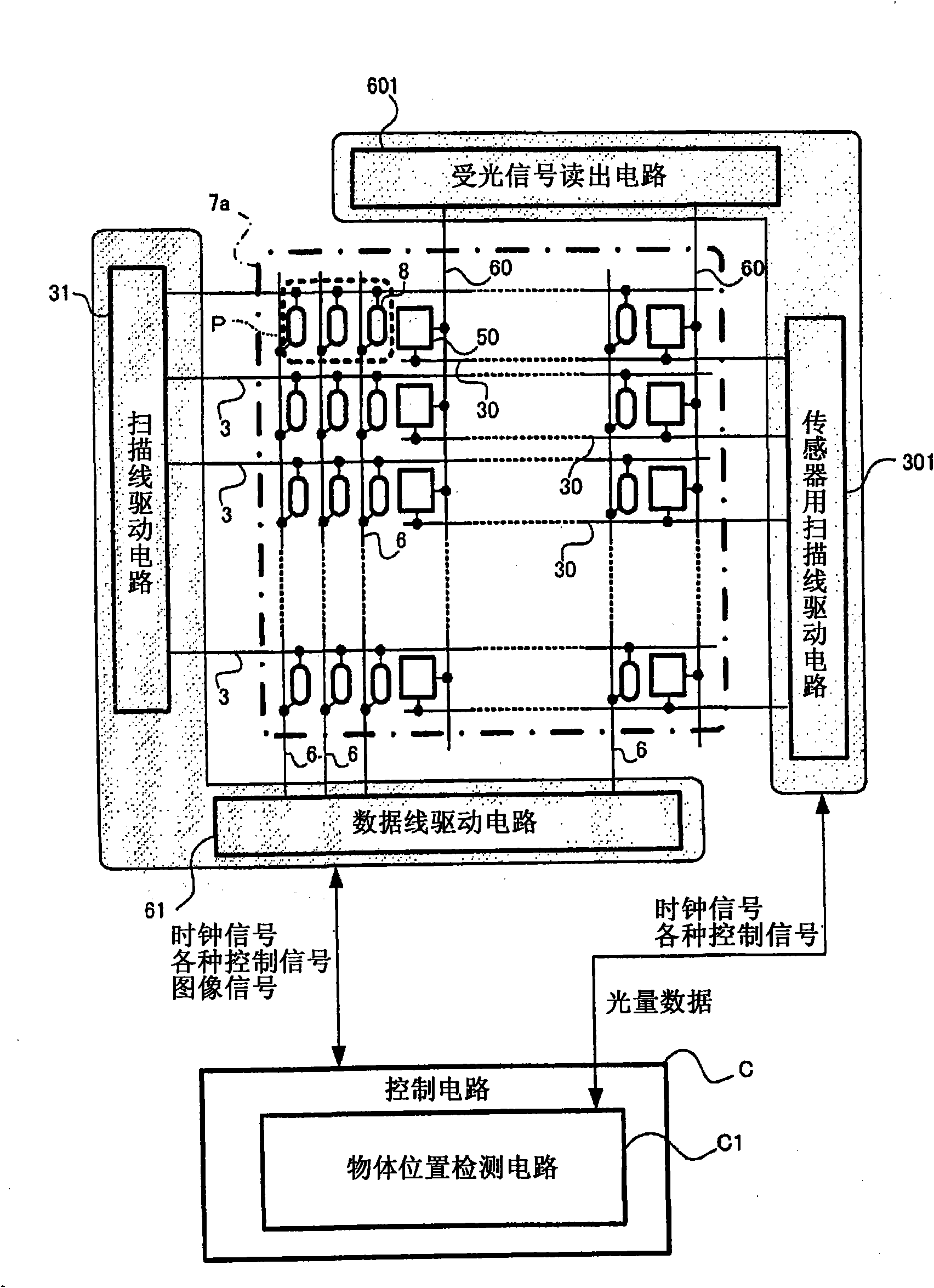
[0072] like figure 1 As shown, the electro-optical device 1 of the first embodiment includes a liquid crystal element (electro-optical element) 8 , scanning lines 3 , data lines 6 , scanning line driving circuit 31 , data line driving circuit 61 , and the like.

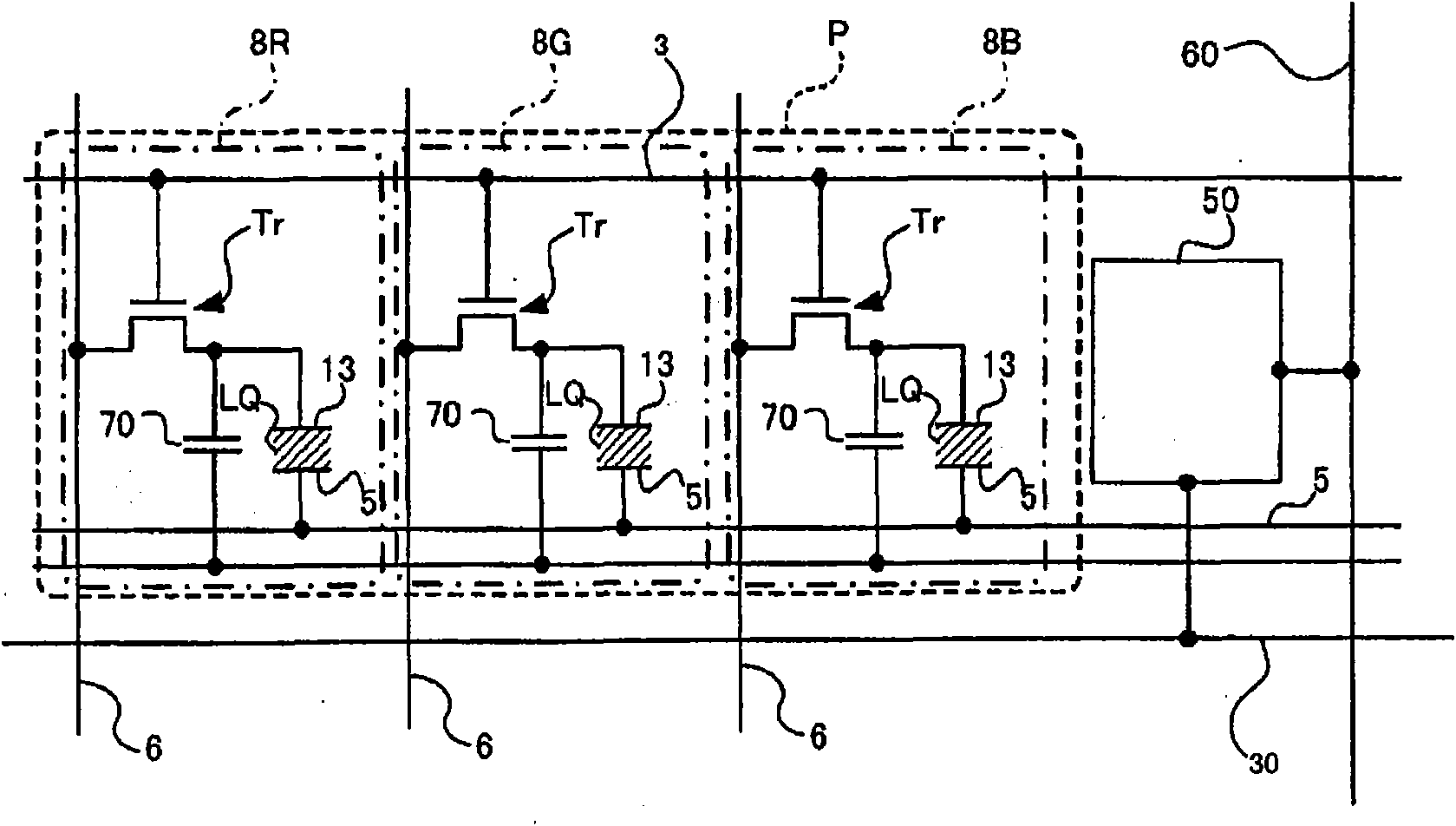
[0073] where the liquid crystal element 8, such as figure 2 As shown in detail in , it is composed of the pixel electrode 13, the counter electrode 5, the storage capacitor 70, and the switching transistor Tr.

[0074] The pixel electrodes 13 are arranged in a matrix on an element substrate not shown in the figure (refer to fig...

no. 2 Embodiment approach

[0118] Below, refer to Figure 8 to Figure 11 A second embodiment of the present invention will be described. In addition, since the configuration of the electro-optical device 1 of the second embodiment and the basic processing related to the object position detection processing are the same as those of the first embodiment, descriptions of overlapping parts will be briefly described or appropriately omitted.

[0119] First, in the second embodiment, if Figure 8 As shown, one light quantity detection element 50 is provided for every twelve liquid crystal elements 8 . However, among 12 liquid crystal elements 8, one group is constituted (refer to Figure 8 The arrangement state of the three liquid crystal elements 8 in symbol P) is the same as that of the first embodiment, and the red, green, and blue light emitting liquid crystal elements 8R, 8G, and 8B are arranged in order from the left in the figure. All 12 liquid crystal elements 8 are arranged according to the arrang...

no. 3 Embodiment approach

[0146] Below, refer to Figure 12 A third embodiment of the present invention will be described. In addition, the configuration of the electro-optical device 1 of the third embodiment and the content of the basic processing related to the object position detection processing are the same as those of the first embodiment, so overlapping parts will be briefly described or appropriately omitted.

[0147] In the third embodiment, Figure 5 Object image readout processing ( Figure 5 The content of step S201) is very characteristic. The treatment is as Figure 12 Proceed as shown.

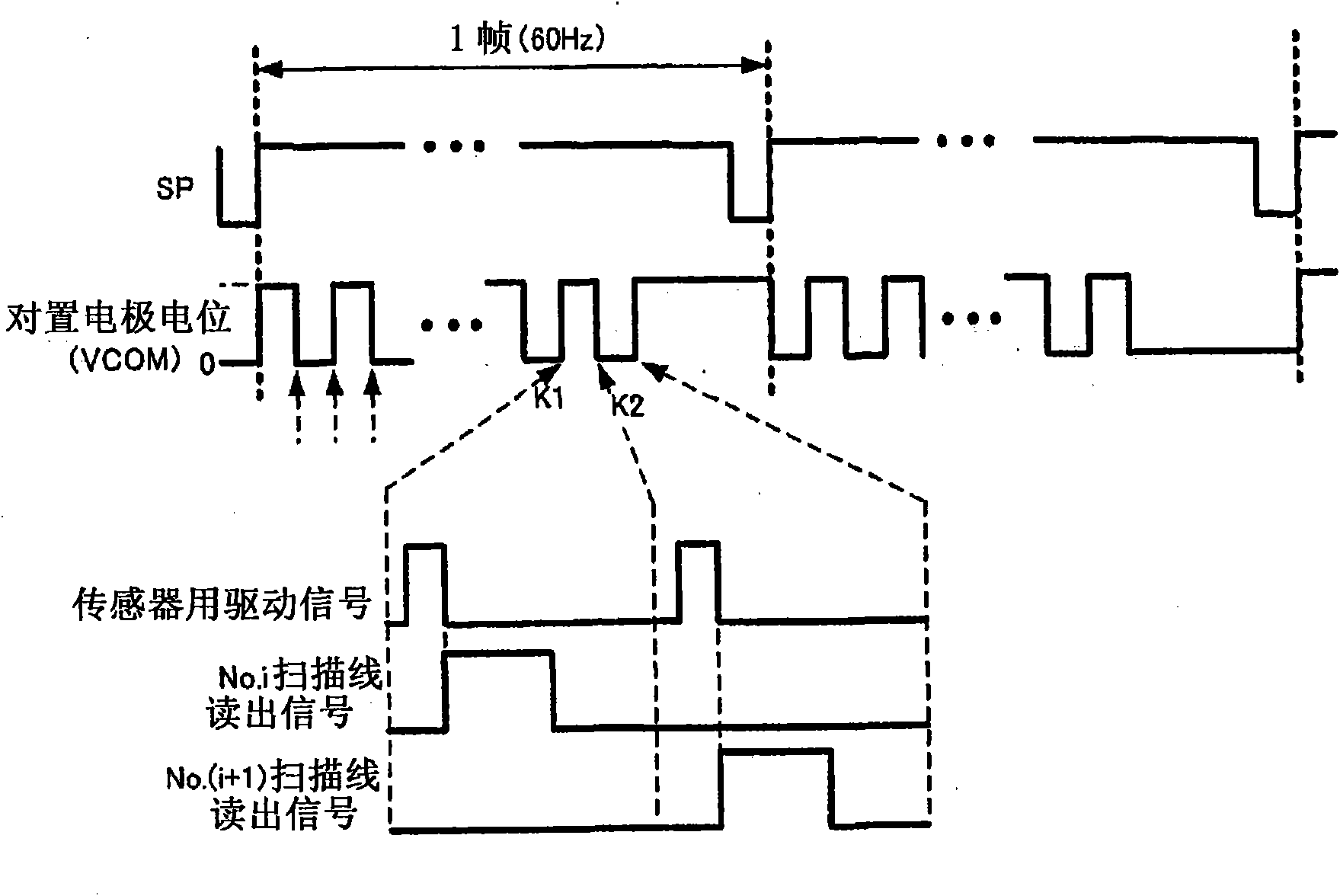
[0148] That is, first, the control circuit C is different from the above-mentioned first and second embodiments in that it can be said that the image readout process for one scanning line is directly started ( Figure 12 step S503). In this regard, it is firstly determined whether or not the polarity inversion of the common potential VCOM has occurred in the two embodiments described above ( Fig...


PUM


Abstract

Provided is an electro-optical device which can prevent image disturbance and can detect the position of the object on the image reading plane with high accuracy. The position detection of fingers, pen points and the like object indicating a certain location on the image reading plane is performed based on the luminous quantity on the entire surface of the image reading plane detected by the luminous quantity detecting element. The electro-optical device includes an electro-optical element that includes a first electrode, a second electrode, and a liquid crystal pinched by the first and secondelectrodes of which the optical characteristic is changed in accordance with supply of a predetermined electric potential. In this case, the polarity of the electric potential difference applied between the first and second electrodes is reverted by the prescribed cycle (in the figure, 'VCOM' denotes the waveform of the electric potential of one side of the first and second electrodes). And, theposition detection is performed based on the measurement result after the measurement result of the luminous quantity detecting element at the polarity reversal time is removed.

Description

technical field [0001] The present invention relates to an electro-optical device such as a liquid crystal display device, electronic equipment, and a position detection method of a pointing object. Background technique [0002] Conventionally, a so-called touch panel has been provided. This is a device capable of conveying the user's intention, command, etc. to the device by detecting the contact position of the user's finger or the like on the image display surface. This touch panel allows intuitive operation, so it is extremely user-friendly, and is widely used as a component of ticket vending machines, bank ATMs, car navigation systems, etc. [0003] Generally, such a touch panel has an integral relationship with an electro-optical device having an electro-optical element such as a liquid crystal display device whose optical characteristics are changed by taking an appropriately supplied potential or current. This electro-optical device has the above-mentioned function...

Claims


Application Information

Patent Timeline
Patent Type & Authority Applications(China)
IPC IPC(8): G02F1/133G06F3/042
CPCG06F3/0412G06F3/042G09G3/36G02F1/133
Inventor 茅野岳人
Owner SEIKO EPSON CORP
Why Eureka
Try Eureka