
Intelligent road tester based on omni-directional vision

An all-round vision and road test instrument technology, applied in positioning, instruments, measuring devices, etc., can solve problems such as poor visibility, limited detection range, and reduced sensor types

Inactive Publication Date: 2010-03-03
ZHEJIANG UNIV OF TECH
View PDF3 Cites 24 Cited by
  • Summary
  • Abstract
  • Description
  • Claims
  • Application Information

AI Technical Summary

Problems solved by technology

Chinese utility model 200620012962.X discloses a vehicle-mounted road test device for diffuse reflection recognition of ground marks, including a test vehicle, a vehicle-mounted computer, a central control computer, and test equipment installed on the road test driveway. There are five diffuse reflection photoelectric sensors on the left front, right front, left rear, right rear and front middle. There are multiple groups of marking strip coding groups composed of five rectangular marking strips on the road test lane. These test equipment include vibration sensors. Obstacle discs with pressure switches, unilateral bridges with upper bridge detection boards with pressure switches, hollow boxes with vibration sensors, booms with vibration sensors, etc., and set up according to the requirements of test equipment and assessment items These signs are recognized by the vehicle identification system to determine the test results, which can reduce the types of sensors; this kind of road test device needs to place many markers on the road test lane, which is not suitable for the test of road driving skills test subjects. In addition There is also the problem of poor visibility in the examination process
[0004] At present, there are also solutions for video road tests, but because the camera device used can only obtain video information in a certain direction of the road test vehicle, the detection range is greatly limited

Method used


Image

  • Intelligent road tester based on omni-directional vision
  • Intelligent road tester based on omni-directional vision
  • Intelligent road tester based on omni-directional vision

Examples


Embodiment Construction

[0119] The present invention is further described with reference to the accompanying drawings.

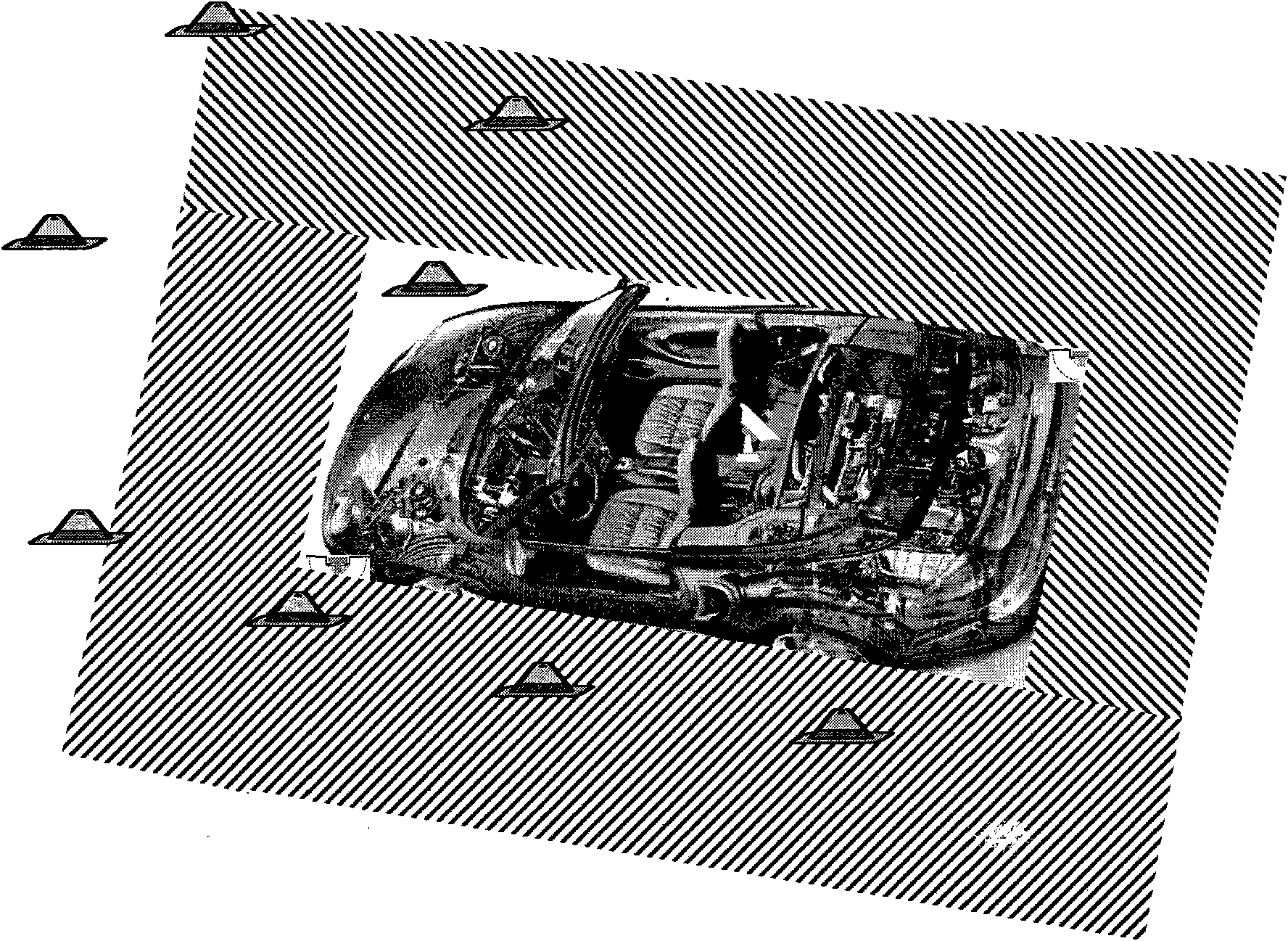
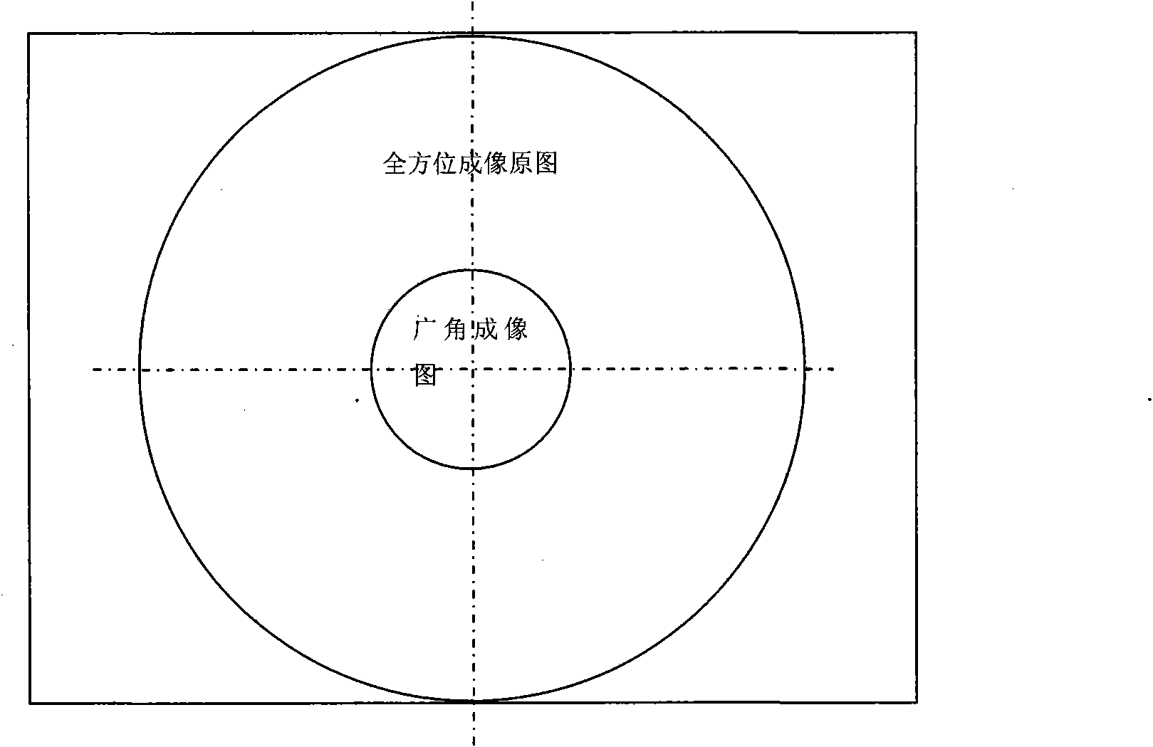
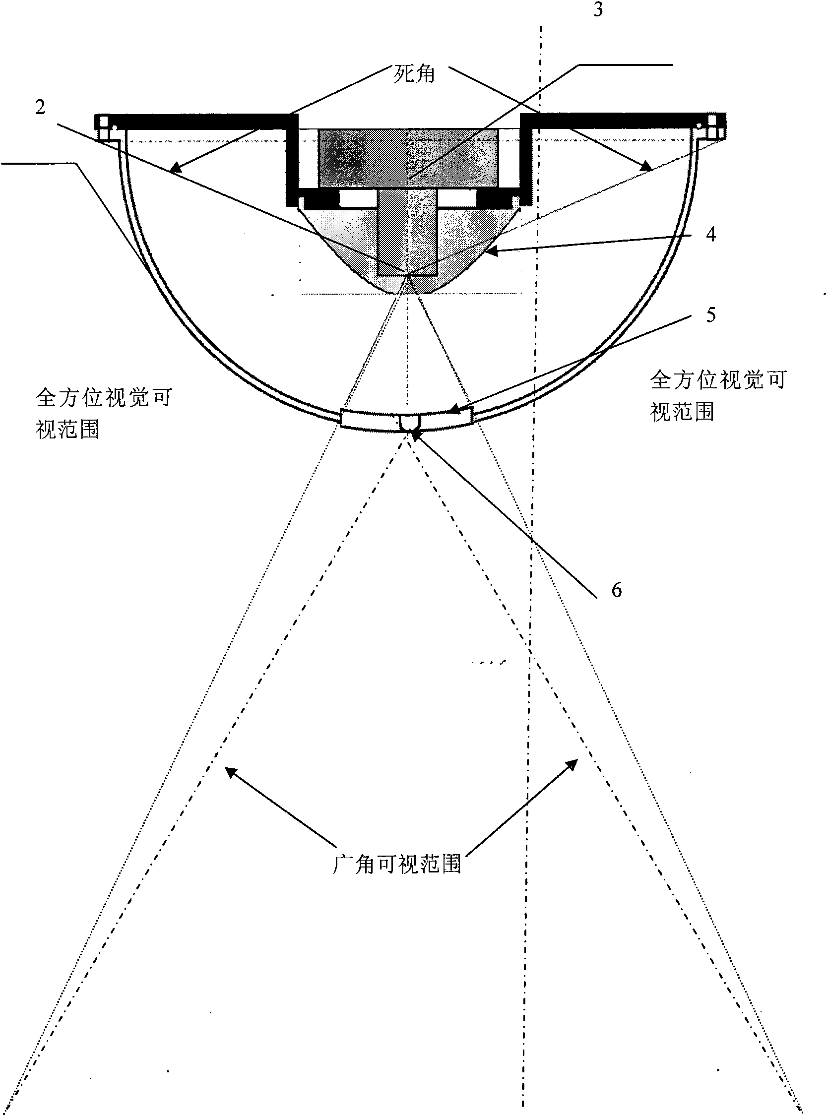
[0120] refer to Figure 1 to Figure 10 , the present invention provides an intelligent road test instrument based on omnidirectional vision. The road test instrument includes: two omnidirectional vision sensors without dead angles arranged on the front and rear sides of the test vehicle, used to obtain the video of the road conditions around the test vehicle. Information; the GPS sensor placed on the test vehicle is used to obtain the spatial position of the test vehicle; the microprocessor placed in the test vehicle is used to process, transmit and store the road condition video information around the test vehicle; placed in the test vehicle The loudspeaker is used to prompt the examinee to take the subject content of the examination below; the two omnidirectional visual sensors without dead angle are connected with the microprocessor through the video interface, and the GPS senso...


PUM


Abstract

An intelligent road tester based on omni-directional vision comprises two omni-directional vision sensors without dead angle, a GPS sensor, a test prompter and a micro-processor, wherein the omni-directional vision sensors are used for obtaining video information of road condition around a vehicle used for road test; the GPS sensor is used for obtaining information of space position of the vehicleused for road test; the test prompter is used for prompting a testee of the content of next subject needing to be tested; and the micro-processor is used for processing, transmitting and memorizing the video information of road condition around the vehicle used for road test; one of the two omni-directional vision sensors is arranged on a support of the front base of the vehicle used for road test so as to obtain the video images in front of and on the left of the vehicle; the other omni-directional vision sensor is arranged on a support of the back base of the vehicle used for road test so as to obtain the video images in back of and on the right of the vehicle; and the GPS sensor, the test prompter and the micro-processor are all arranged in the vehicle. The intelligent road tester based on omni-directional vision can accurately record and judge the real capability of a driver operating and driving a motor vehicle, can conduct on-vehicle test instead of a tester, and has strong practicability.

Description

technical field [0001] The invention belongs to the application of omnidirectional vision sensor technology, image recognition technology, GPS positioning and wireless transmission technology in road test. Background technique [0002] According to the requirements stipulated in Decree No. 91 of the Ministry of Public Security of the People's Republic of China, all candidates who apply for a motor vehicle driving license need to take the test subjects of field driving skills test and road driving skills test subjects. The subjects of field driving skills test include: pile test, Stopping and starting at fixed points on ramps, parking on the side, passing unilateral bridges, driving on curves, turning at right angles, passing through gates with limited width at speed limits, passing continuous obstacles, adding and subtracting gears at 100 meters, driving on undulating roads; road driving skills test subjects include: Getting on board, starting off, driving straight, changing...

Claims


Application Information

Patent Timeline
IPC IPC(8): G09B19/16G01S5/02
Inventor 汤一平汤晓燕俞立杨冠宝姜军
Owner ZHEJIANG UNIV OF TECH
Learn More