

Sequence generation and mapping method of reference signals and transmission device
A technology of reference signal and mapping method, which is applied in the direction of signaling distribution, transmission path sub-channel distribution, electrical components, etc., and can solve the problems of reference signal sequence generation and mapping method not described
- Summary
- Abstract
- Description
- Claims
- Application Information
AI Technical Summary
Problems solved by technology
Method used
Image

Examples
no. 1 example
[0222] In this embodiment, the number of layers is 2, and reference signal #0 and reference signal #1 are sent respectively.
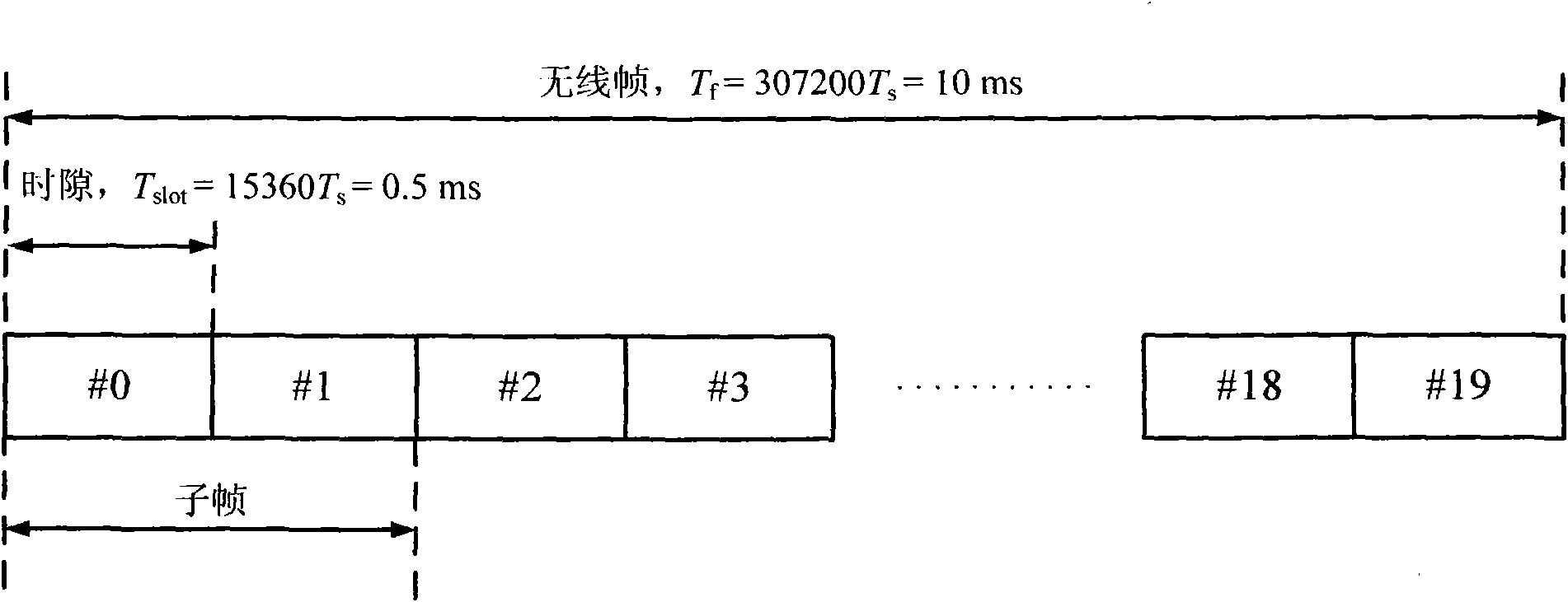
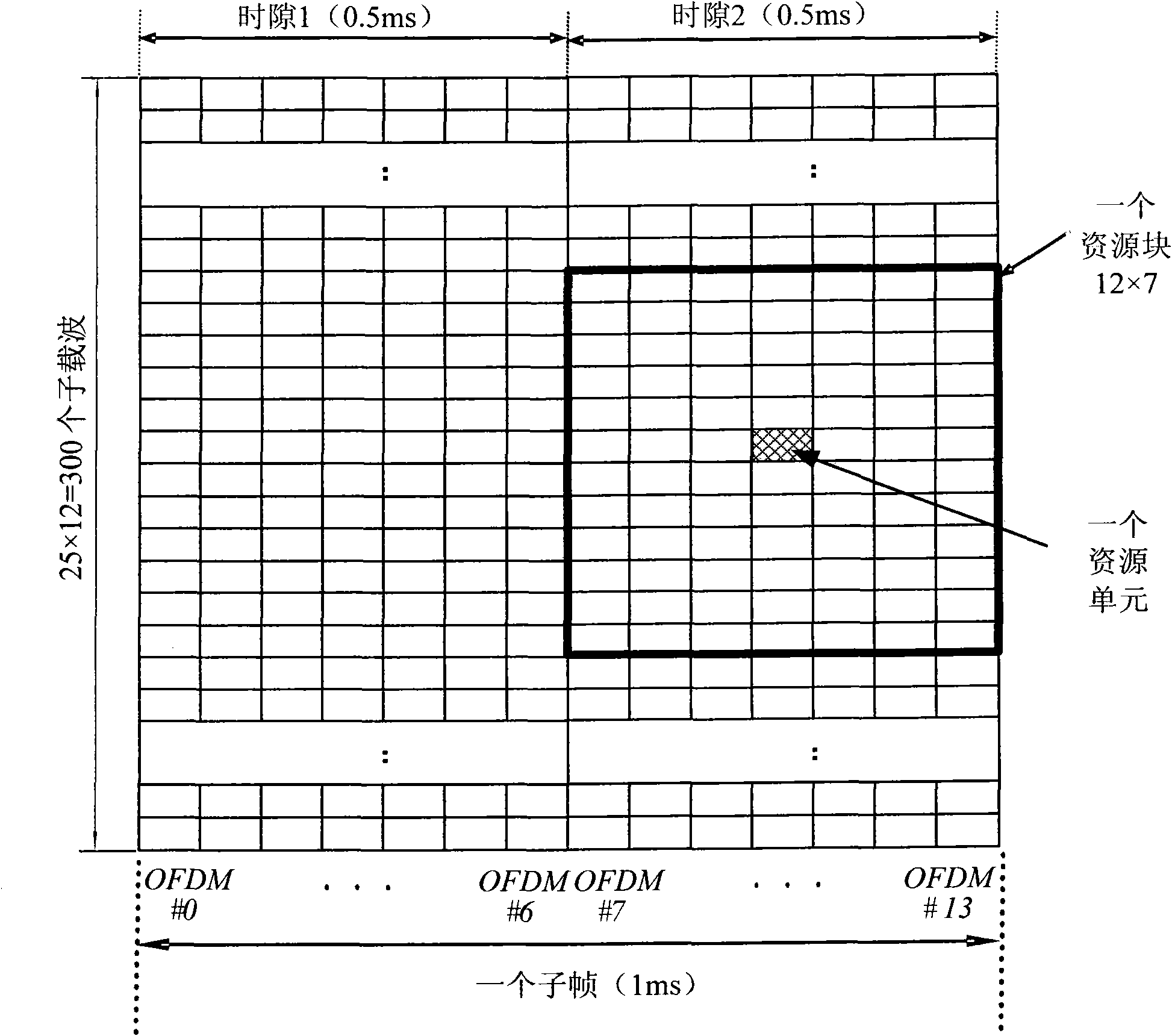
[0223] Reference signal #0 is located on the first, sixth, and eleventh subcarriers of the penultimate symbol of the first slot in the subframe and on the first, sixth, and eleventh subcarriers of the penultimate symbol of the first slot in the subframe On subcarriers, and on the first, sixth, and eleventh subcarriers of the penultimate symbol of the second slot and on the first, sixth, and eleventh subcarriers of the penultimate symbol ; The corresponding orthogonal code is {1, 1, 1, 1}.
[0224] Reference signal #1, located on the first, sixth, and eleventh subcarriers of the penultimate symbol of the first slot in the subframe and on the first, sixth, and eleventh subcarriers of the penultimate symbol subcarriers, and the first, sixth, and eleventh subcarriers of the penultimate symbol of the second slot and the first, sixth, and eleventh subcarrie...
no. 2 example
[0291] In this embodiment, the number of layers is four, and reference signal #0, reference signal #1, reference signal #2, and reference signal #3 are sent respectively.
[0292] Reference signal #0, located on the first, sixth, and eleventh subcarriers of the penultimate symbol of the first slot in the subframe and the first, sixth, and eleventh subcarriers of the penultimate symbol subcarriers, and the first, sixth, and eleventh subcarriers of the penultimate symbol of the second slot and the first, sixth, and eleventh subcarriers of the penultimate symbol above; the corresponding orthogonal code is {1, 1, 1, 1}.
[0293] Reference signal #1, located on the first, sixth, and eleventh subcarriers of the penultimate symbol of the first slot in the subframe and on the first, sixth, and eleventh subcarriers of the penultimate symbol subcarriers, and the first, sixth, and eleventh subcarriers of the penultimate symbol of the second slot and the first, sixth, and eleventh subcar...
no. 3 example
[0362] In this embodiment, the number of layers is 8, corresponding to reference signal #0, reference signal #1, reference signal #2, reference signal #3, reference signal #4, reference signal #5, reference signal #6, reference signal # 7.
[0363] Reference signal #0, located on the first, sixth, and eleventh subcarriers of the penultimate symbol of the first slot in the subframe and the first, sixth, and eleventh subcarriers of the penultimate symbol subcarriers, and the first, sixth, and eleventh subcarriers of the penultimate symbol of the second slot and the first, sixth, and eleventh subcarriers of the penultimate symbol above; the corresponding orthogonal code is {1, 1, 1, 1}.
[0364] Reference signal #1, located on the first, sixth, and eleventh subcarriers of the penultimate symbol of the first slot in the subframe and on the first, sixth, and eleventh subcarriers of the penultimate symbol subcarriers, and the first, sixth, and eleventh subcarriers of the penultima...
PUM
 Abstract
Description
Claims
Application Information