Physical layer secret optical fiber communication system based on chaotic phase encryption

An optical fiber communication system and physical layer technology, applied in the field of optical communication, can solve the problems of limiting the transmission rate of chaotic optical communication, weakening the security of the communication system, leaking the length of the outer cavity, etc., to achieve complete disturbance and correct recovery, and ensure security. and privacy, to achieve the effect of encryption and decryption

Active Publication Date: 2020-06-12
UNIV OF ELECTRONICS SCI & TECH OF CHINA
View PDF10 Cites 22 Cited by
  • Summary
  • Abstract
  • Description
  • Claims
  • Application Information

AI Technical Summary

Problems solved by technology

[0004] However, after in-depth research, scholars have found that the chaotic laser generated by the external cavity semiconductor laser has safety defects. Due to the existence of the external cavity resonance, the autocorrelation curve of the generated chaotic signal has an obvious correlation peak at the external cavity period. It is called a time-delay tag. The time-delay tag leaks the length of the external cavity, so that the interceptor can use this key structural information to reconstruct the chaotic carrier signal, and then crack the transmitted information, weakening the security of the communication system.
On the other hand, the inherent relaxation oscillation of external cavity semiconductor lasers leads to chaotic laser bandwidth of only a few GHz. In chaotic optical communication, chaotic laser is used as a carrier to hide the transmitted optical information. The limited chaotic carrier bandwidth limits the transmission of chaotic optical communication. rate, making it difficult to be compatible with existing high-speed fiber optic communication systems

Method used


Image

  • Physical layer secret optical fiber communication system based on chaotic phase encryption
  • Physical layer secret optical fiber communication system based on chaotic phase encryption
  • Physical layer secret optical fiber communication system based on chaotic phase encryption

Examples


Embodiment

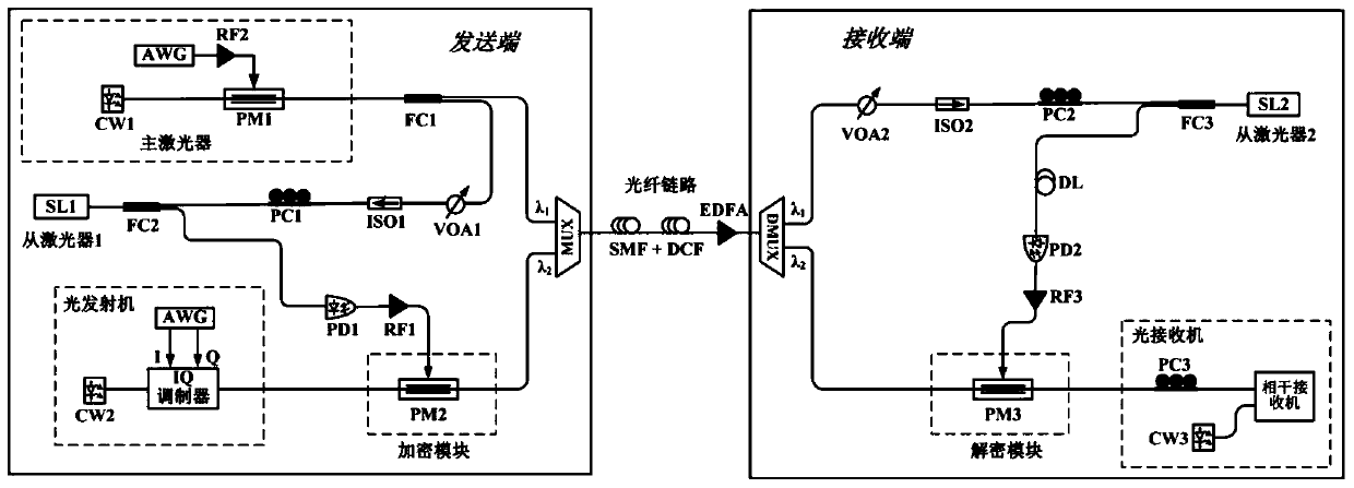
[0033] figure 1 It is a structure diagram of a specific implementation mode of a physical layer security optical fiber communication system based on chaotic phase encryption in the present invention.

[0034] In this example, if figure 1 As shown, a physical layer security optical fiber communication system based on chaotic phase encryption of the present invention includes: a sending end, a receiving end, and an optical fiber link connecting the sending end and the receiving end;

[0035] The sending end includes: master laser, slave laser SL1, optical transmitter, fiber coupler FC1, polarization controller PC1, fiber isolator ISO1, adjustable optical attenuator VOA1, photodetector PD1, radio frequency amplifier RF1, encryption module and wave Demultiplexer MUX;

[0036] In this embodiment, the distributed feedback semiconductor laser DFB is selected from the laser SL1; the signal sent by the optical transmitter is any high-order modulated optical signal, such as quadrature...


PUM


Abstract

The invention discloses a physical layer secret optical fiber communication system based on chaotic phase encryption, and the system comprises the steps: dividing a broadband random light source generated by a main laser into two identical optical signals, and respectively injecting the two optical signals into slave lasers of two communication sides, thereby generating a synchronous chaotic signal; and then the generated synchronous chaotic signal is used as a phase modulator driving signal, and high-speed optical signals generated by high-order modulation are encrypted and decrypted at a sending end and a receiving end.

Description

technical field [0001] The invention belongs to the technical field of optical communication, and more specifically relates to a physical layer security optical fiber communication system based on chaotic phase encryption. Background technique [0002] With the rise of the Internet age and the rapid development of information technology, people have higher and higher requirements for efficient and fast information transmission carriers and technologies. Due to its large communication capacity, long transmission distance, good transmission quality, and less crosstalk between signals, optical fiber communication has become the leading transmission technology for information networks in the 21st century. However, while optical fiber communication brings great convenience to people, its openness and sharing characteristics also make information security problems increasingly severe. How to improve the security of optical fiber communication systems has become a hot research issu...

Claims


Application Information

Patent Timeline
Patent Type & Authority Applications(China)
IPC IPC(8): H04B10/85H04L9/00
CPCH04B10/85H04L9/001
Inventor 江宁赵安可邱昆
Owner UNIV OF ELECTRONICS SCI & TECH OF CHINA
Why Eureka
Try Eureka