Method for configuring the link maximum transmission unit (MTU) in a user equipment (UE).

A technology of maximum transmission unit, user equipment, applied in the direction of transmission system, data exchange through path configuration, electrical components, etc., can solve the problems of data loss, integrity and potential confidentiality destruction, etc.

Active Publication Date: 2010-03-03
TELEFON AB LM ERICSSON (PUBL)
View PDF0 Cites 16 Cited by
  • Summary
  • Abstract
  • Description
  • Claims
  • Application Information

AI Technical Summary

Problems solved by technology

False reassembly results in at least further data loss and integrity (and potentially confidentiality) breaches that can be detected by the receiver

Method used


Image

  • Method for configuring the link maximum transmission unit (MTU) in a user equipment (UE).
  • Method for configuring the link maximum transmission unit (MTU) in a user equipment (UE).
  • Method for configuring the link maximum transmission unit (MTU) in a user equipment (UE).

Examples


no. 1 example

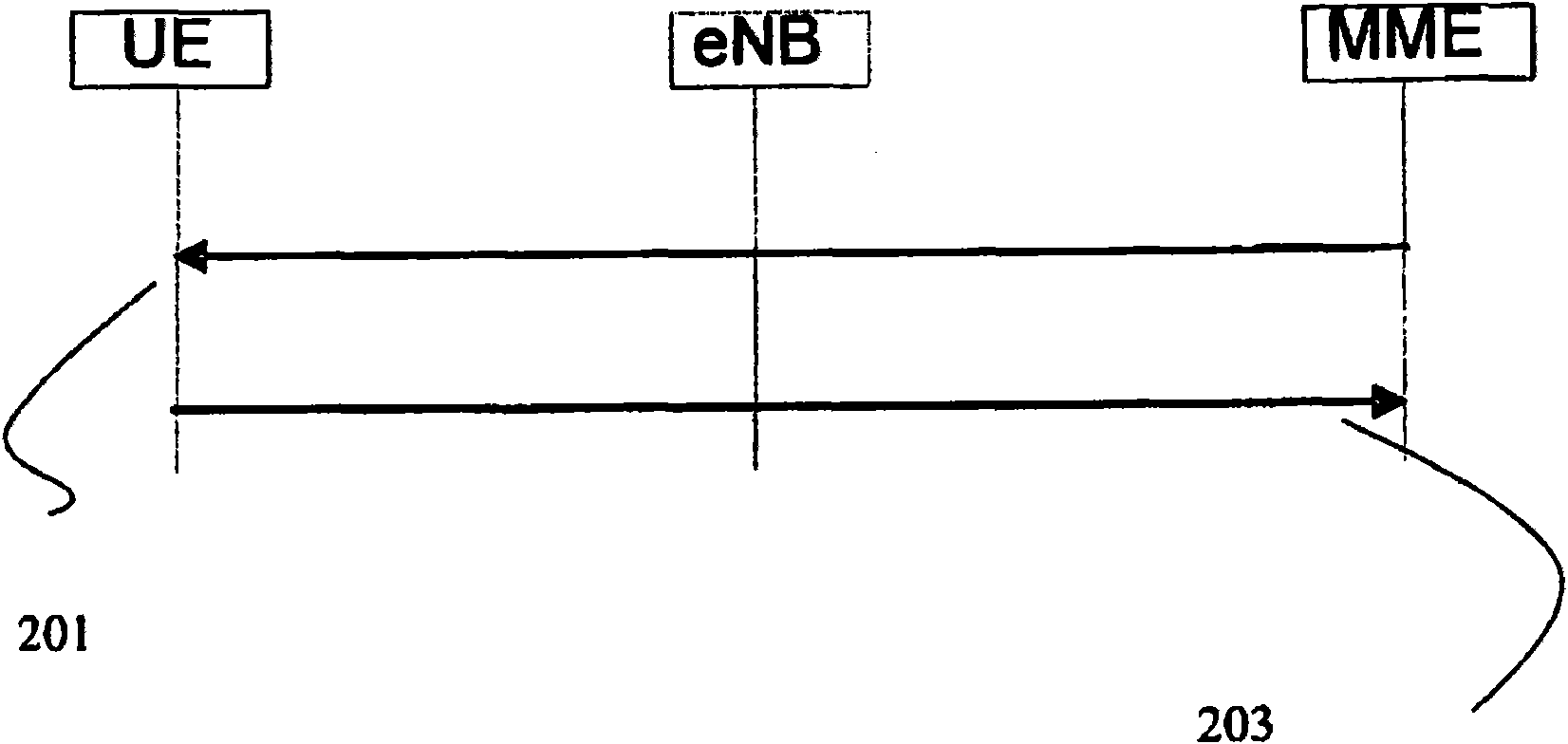
[0037]According to a first embodiment, the link MTU is notified in a Non-Access Stratum (NAS) message from a Mobility Management Entity (MME). The advertised link MTU is explicitly indicated because it conceptually represents the MTU supported by the SAE bearer service. exist figure 2 The NAS signaling for SAE bearer establishment and modification is illustrated in . Therefore, first in message 201, the Non-Access Stratum (NAS) message from the Mobility Management Entity (MME) includes the SAE bearer setup / modification request and the link MTU. In response to message 201, the UE transmits a NAS message 203 to confirm that SAE bearer setup / modification is complete.

[0038] According to one embodiment of the invention, the MME signaling in the NAS SAE Bearer Setup / Modification Request message (or similar) can represent a chain of MTUs for paths used for SAE bearer services in the whole or part of a specific SAE / LTE network Road MTU. For example, the advertised link MTU can...


PUM


Abstract

In a System Architecture Evolution / Long Term Evolution (SAE/LTE) radio network, the network is set to configure the link MTU in the UE for each bearer where the network- configured link MTU can represent an MTU of a path for a SAE bearer service in complete or part of a particular SAE/LTE network.

Description

technical field [0001] The present invention relates to a method and an arrangement in a telecommunication system, in particular to a method and an arrangement for network-controlled configuration of a link maximum transmission unit (MTU) in a user equipment (UE). Background technique [0002] In the 3rd Generation Partnership Project (3GPP), a current work in progress is UTRAN Long Term Evolution (LTE). The System Architecture Evolution / Long Term Evolution (SAE / LTE) architecture moving PDCP, user plane encryption, and header compression to the enhanced Node B (eNB) changes the need to handle the length of S1-U (and X2-U) frames, Because the length of the S1-U (and X2-U) frame will increase considerably later. Therefore, an appropriate solution to deal with the length of the Maximum Transmission Unit (MTU) is necessary. At the same time, the ability to minimize the probability of S1-U frames being fragmented is slightly improved. [0003] The following issues are related ...

Claims


Application Information

Patent Timeline
Patent Type & Authority Applications(China)
IPC IPC(8): H04L12/46H04L47/36
CPCH04L29/06095H04W80/06H04W84/042H04W80/04H04L69/166H04W28/16H04L29/06136H04L69/16H04L47/36H04W28/02H04W4/18H04L12/46H04W72/23
Inventor T·库宁加斯
Owner TELEFON AB LM ERICSSON (PUBL)
Why Eureka
Try Eureka