Prefabricated part composite cement soil wall and construction method thereof

A prefabricated component and composite cement technology, applied in infrastructure engineering, sheet pile walls, buildings, etc., can solve problems such as troublesome steel removal, poor stress characteristics, waste of steel consumption, etc., to save the cost of mechanical research and development, improve the surrounding The form of protective structure and the effect of meeting the needs of engineering construction

Active Publication Date: 2010-03-10
SHANGHAI CONSTRUCTION GROUP
View PDF0 Cites 8 Cited by
  • Summary
  • Abstract
  • Description
  • Claims
  • Application Information

AI Technical Summary

Problems solved by technology

The disadvantages of SMW construction method piles are: when the construction period is longer than 6 months, the rental cost of section steel will increase, and the removal of section steel is more troublesome
[0004] Among them, the bored pile enclosure belongs to the column type retaining wall, which cannot stop water itself, and needs to be installed with a water-stop curtain. The strength of the force needs to increase the input of steel bars, which will cause a waste of part of the amount of steel bars
[0005] Among them, the disadvantages of the underground diaphragm wall are: the cost is high, and the construction process is complicated
[0006] To sum up, the current form of enclosure structure in my country's underground engineering construction cannot fully meet the needs of engineering construction. Therefore, it is urgent to develop a form of enclosure structure with low cost, low environmental impact, safety, and construction technology

Method used


Image

  • Prefabricated part composite cement soil wall and construction method thereof
  • Prefabricated part composite cement soil wall and construction method thereof
  • Prefabricated part composite cement soil wall and construction method thereof

Examples


Embodiment 1

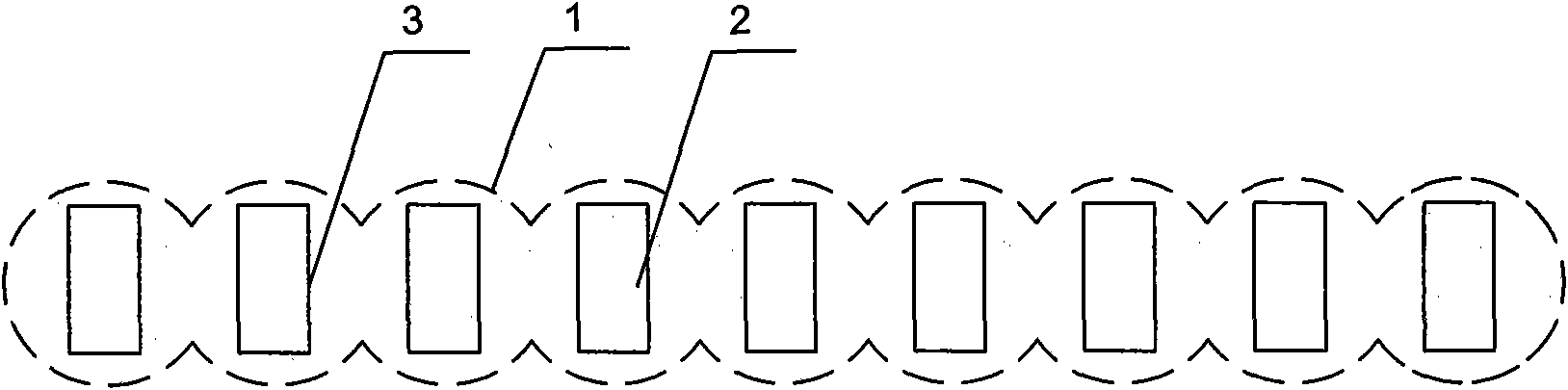
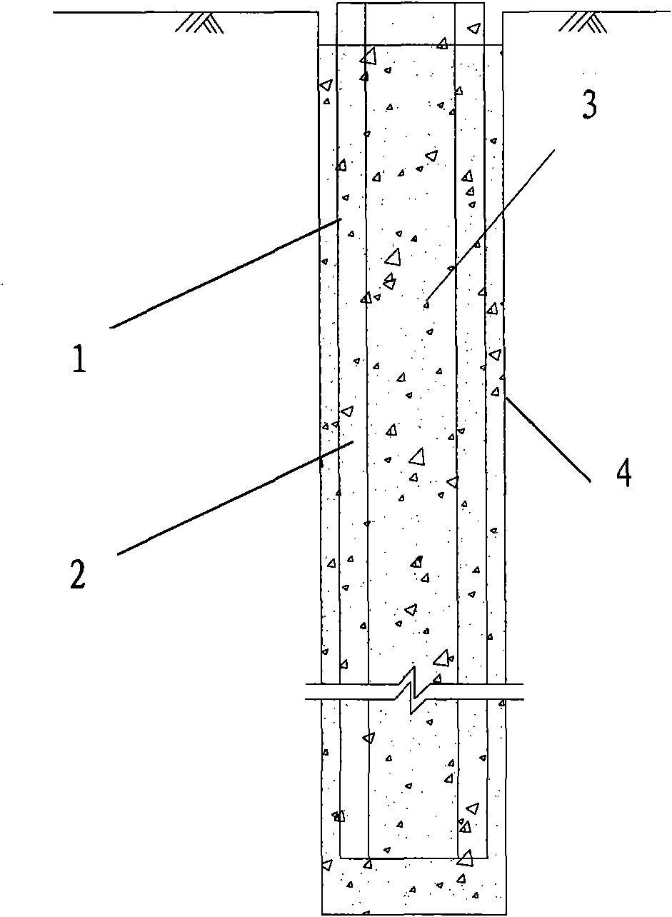
[0056] see Figure 1a , Figure 1b , this kind of prefabricated component composite cement-soil wall includes several cement-soil piles 1 containing cement-soil, adjacent cement-soil piles 1 are interlocked, and each cement-soil pile 1 is inserted with a long prefabricated Build 3. The cement-soil piles 1 are constructed using a three-axis cement-soil mixing pile construction machine, and every three cement-soil piles 1 are constructed simultaneously. Every three cement-soil piles 1 form a pile unit group, and each pile unit group 1 includes a head pile, a middle pile and a tail pile in turn, and adjacent piles are interlocked. During construction, first divide all cement-soil piles into several pile unit groups. All pile unit groups are divided into first order pile unit groups and second order pile unit groups. The first sequential pile unit group and the second sequential pile unit group are arranged at intervals from each other. The first pile of the second sequence pi...

Embodiment 2

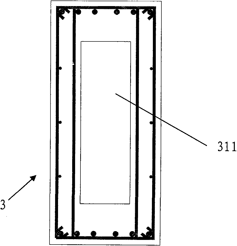
[0061] The difference between this embodiment and embodiment 1 is that the prefabricated component 3 is a steel-concrete composite beam component, that is, a steel-concrete composite structure. Compared with the steel structure, this steel-concrete composite structure saves steel, enhances the rigidity of components or buildings, and improves the deformation resistance. Compared with ordinary reinforced concrete structures, this steel-concrete composite structure reduces the weight, increases the ductility of components, and has higher strength, which can give full play to the material properties of steel and concrete. , so that the unity of technology and economy can be achieved.

[0062] see figure 2 , the specific structure of the steel and concrete composite beam member is as follows: it includes an H-shaped steel 321 and two reinforced concrete slabs 322 . The reinforced concrete slab 322 consists of a concrete slab provided with several steel bars. The H-shaped steel...

Embodiment 3

[0065] see Figure 3a and Figure 3b , The difference between this embodiment and Embodiment 1 is that: the prefabricated component 3 is a steel and concrete composite truss component. The steel and concrete composite truss member includes a reinforced concrete slab 332 and a steel truss 321 . The steel truss 321 is composed of upper and lower chords 3211, 3212 connected by several webs 3213. The reinforced concrete slab 332 is fixedly connected to the upper side of the upper chord 3211 of the steel truss 321 . The reinforced concrete slab 332 is connected to the upper chord 3211 of the steel truss 321 by bolts. The upper and lower chords 3211 and 3212 of the steel truss 321 can be made of angle steel, and the web 3213 can be made of steel pipes.

[0066] This steel and concrete composite truss beam member is a new type of composite structure, which has good mechanical properties and good economy, and can be widely used in long-span, heavy-load high-rise buildings and supe...


PUM

PropertyMeasurementUnit
diameteraaaaaaaaaa

Abstract

The invention relates to the field of a novel space enclosing structure in a design and construction method of deep foundation, in particular to a prefabricated part composite cement soil wall and a construction method thereof. The prefabricated part composite cement soil wall comprises a plurality of cement soil piles which are internally provided with cement soil; the adjoining cement soil pilesare occluded with each other; and each cement soil pile is internally inserted with a strip-shaped prefabricated part. The construction method of the prefabricated part composite cement soil wall comprises the following steps of: locating and setting lines; excavating guide ways; setting drillers; locating the drillers and constructing the cement soil piles; setting locating frames for the piles;and inserting the prefabricated parts. The invention effectively reduces the construction cost on the basis of meeting the force requirement of the space enclosing structure of trenches and guaranteeing the security. The invention belongs to a novel space enclosing structure form with low cost, less environmental impact, safety and high efficiency, and can perfect the space enclosing structure form in the field of underground construction, so as to further meet the requirement of engineering construction.

Description

technical field [0001] The invention relates to the field of novel enclosure structures in deep foundation design and construction methods, in particular to underground walls and construction methods thereof. Background technique [0002] The enclosure structure of the foundation pit is mainly used to withstand the earth pressure and water pressure generated by the excavation and unloading of the foundation pit, and transmit this pressure to the support. The enclosure structure of the foundation pit is a retaining wall structure to stabilize the foundation pit. At present, the more commonly used foundation pit enclosure structures suitable for excavation depths of more than 10m in soft soil areas include: SMW piles, bored piles, and underground diaphragm walls. [0003] Among them, the SMW construction method pile is a composite soil-retaining and water-stop structure formed by inserting section steel into the continuously socketed three-axis cement-soil mixing pile. The f...

Claims


Application Information

Patent Timeline
Patent Type & Authority Applications(China)
IPC IPC(8): E02D5/20
Inventor 胡玉银严时汾王美华王祺国周蓉峰费春佘清雅
Owner SHANGHAI CONSTRUCTION GROUP
Why Eureka
Try Eureka