
Incongruous transmission lifter

A lifter, gear shaft technology, applied in the direction of transmission, friction transmission, belt/chain/gear, etc., can solve the problems of high maintenance cost, poor operation stability, poor operability, etc., to achieve reliable operation, stable performance, noise small effect

Inactive Publication Date: 2010-03-10
瑞安市茂兴包装机械有限公司
View PDF0 Cites 0 Cited by
  • Summary
  • Abstract
  • Description
  • Claims
  • Application Information

AI Technical Summary

Problems solved by technology

[0002] Traditional hydraulic and pneumatic molding machines are equipped with hydraulic or pneumatic lifters to complete operations such as mechanical clamping and hollow molding, but the existing hydraulic or pneumatic lifters have complex structures and are expensive, and the hydraulic or pneumatic lifters are used for a long time After that, there will often be liquid or air leakage, resulting in slower lifting transmission speed, requiring regular maintenance and replenishment of liquid and air, resulting in high maintenance costs
In addition, on equipment that requires high-precision numerical control transmission and lifting, hydraulic and pneumatic lifters cannot achieve sufficient control accuracy and have poor operability
[0003] In addition, there is also an existing lifter that performs lifting transmission through a single-sided rack and pinion shaft. Its operating positioning is poor, and the rack is easily displaced, resulting in failures, poor operating stability, and short life.

Method used


Image

  • Incongruous transmission lifter
  • Incongruous transmission lifter

Examples


Embodiment Construction

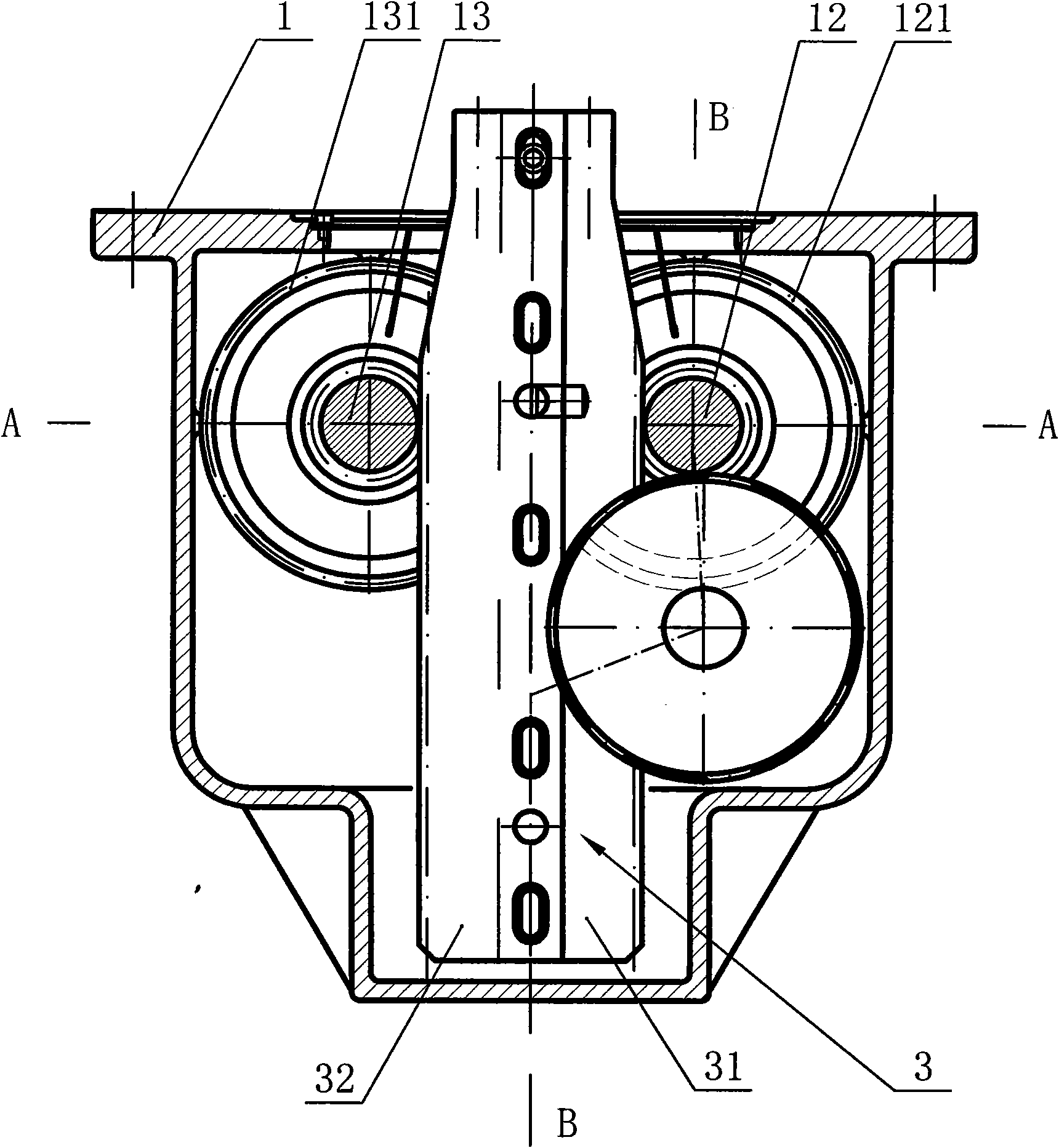
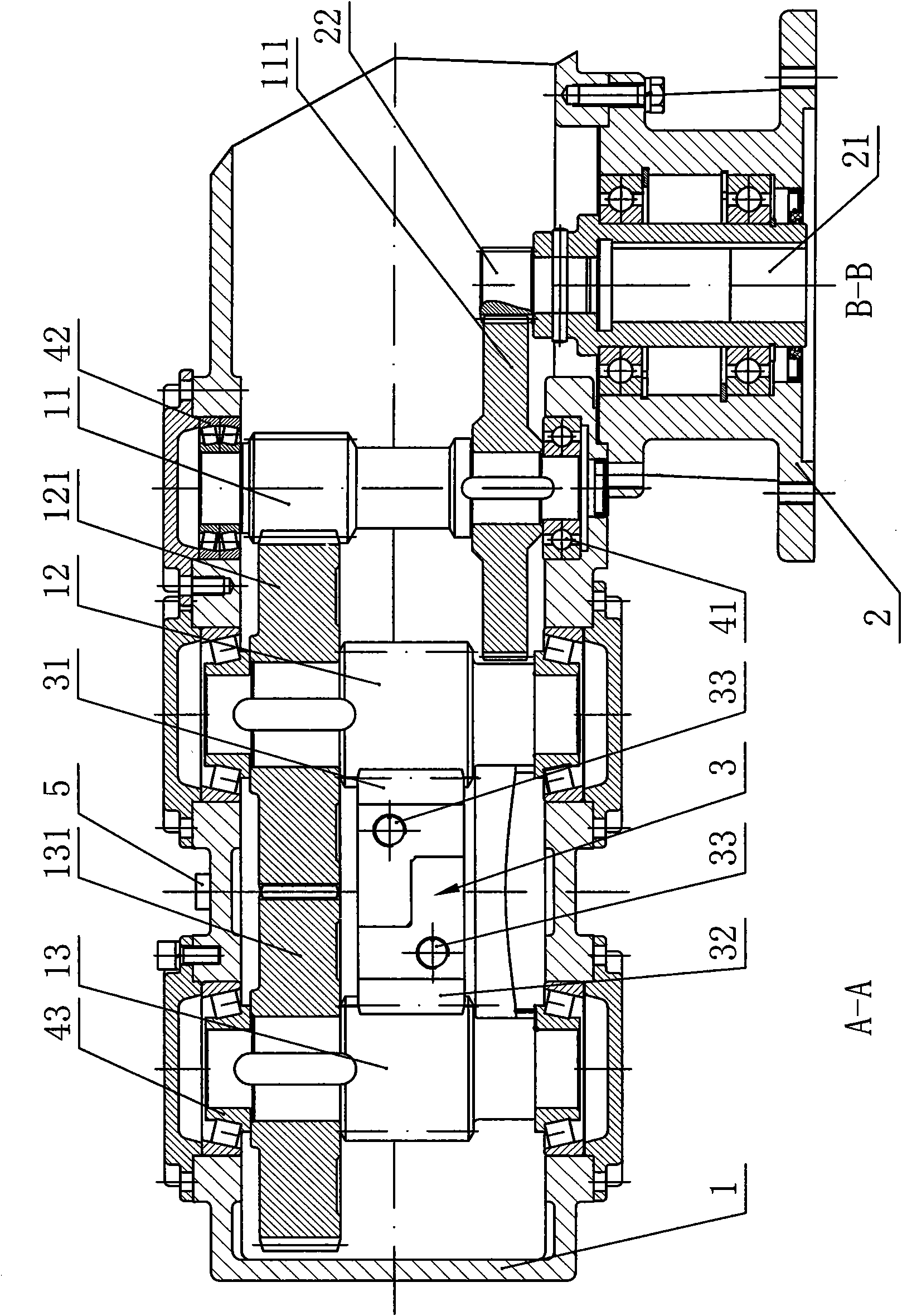
[0013] Such as Figure 1-2 The specific embodiment of the present invention shown includes a box body 1, an input flange 2, and a double-sided rack 3. The input flange 2 is fixed on the box body 1 and the input flange 2 is provided with Input shaft 21, the inner end of the input shaft 21 is provided with an input gear 22, the box body 1 is provided with a gear shaft I 11, a gear shaft II 12, and a gear shaft III 13, and the gear shaft I 11 is fixedly connected The gear I 111 meshed with the input gear 22 of the input shaft 21 is connected, the gear II 121 is fixedly connected to the gear shaft II 12, and the gear III 131 is fixedly connected to the gear shaft III 13. II 12 is consistent with the transmission ratio of gear III 13, and the gear shaft II and gear shaft III have the same transmission ratio, so that the power is transmitted to gear III 13 through gear II 12, so that the transmission of gear shaft II 12 and gear shaft III 13 The speed is the same and the direction ...


PUM


Abstract

The invention relates to an incongruous transmission lifter, which comprises a box body, an input flange and a double-sided rack. The input flange is fixedly arranged on the box body, an input shaft is arranged on the input flange and an input gear is positioned at the inner end of the input shaft. The box body is rotationally provided with a gear shaft I, a gear shaft II and a gear shaft III, wherein the gear shaft I is fixedly linked with a gear I engaged with the input gear of the input shaft, the gear shaft II is fixedly linked with a gear II, and the gear shaft III is fixedly linked witha gear III. The gear shaft I and the gear shaft III are arranged at two sides of the gear shaft II, and the two ends of the gear II on the gear shaft II are respectively matched with the gear shaft Iand the gear shaft III in a meshed linkage way. The double-sided rack consists of a rack I and a rack II, which are integrated by opposite butt joint. The double-sided rack is arranged between the gear shaft II and the gear shaft III, and the rack I and the rack II thereof are respectively matched with the gear shaft II and the gear shaft III at two sides thereof in a meshed linkage way. The incongruous transmission lifter has the advantages of stable performance, reliable operation and small noise and the like.

Description

technical field [0001] The invention relates to a mechanical transmission device, in particular to a different-direction transmission lifter. Background technique [0002] Traditional hydraulic and pneumatic molding machines are equipped with hydraulic or pneumatic lifters to complete operations such as mechanical clamping and hollow molding, but the existing hydraulic or pneumatic lifters have complex structures and are expensive, and the hydraulic or pneumatic lifters are used for a long time After that, liquid or air leakage often occurs, resulting in slower lifting transmission speed, requiring regular maintenance and replenishment of liquid and air, resulting in high maintenance costs. In addition, on equipment that requires high-precision CNC transmission and lifting, hydraulic and pneumatic lifters cannot achieve sufficient control accuracy and have poor operability. [0003] In addition, there is also an existing lifter that performs lifting transmission through a s...

Claims


Application Information

Patent Timeline
Patent Type & Authority Applications(China)
IPC IPC(8): F16H19/04
Inventor 张茂兴
Owner 瑞安市茂兴包装机械有限公司
Learn More