Insulating tube type busbar and manufacturing method thereof

A processing method and technology of insulating tubes, applied in the direction of insulated cables, insulated conductors, non-insulated conductors, etc., can solve the problems of reduced current-carrying capacity and cracking of ribs, achieve the reduction of outer diameter, facilitate bending and other processing, and improve current-carrying capacity Effect

Active Publication Date: 2010-03-10
SHANGHAI XIBANG ELECTRIC
View PDF1 Cites 5 Cited by
  • Summary
  • Abstract
  • Description
  • Claims
  • Application Information

AI Technical Summary

Problems solved by technology

However, if the ribs set on the inner wall of this technology will crac

Method used


Image

  • Insulating tube type busbar and manufacturing method thereof
  • Insulating tube type busbar and manufacturing method thereof
  • Insulating tube type busbar and manufacturing method thereof

Examples


Embodiment 1

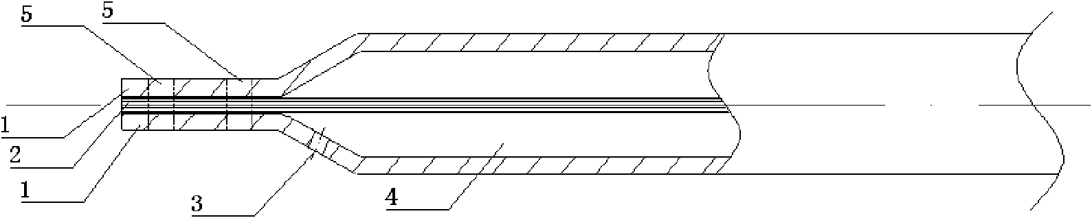
[0028] As shown in Figure 1, the insulating tubular busbar with a current of 4000A and the processing method for inserting wires inside it

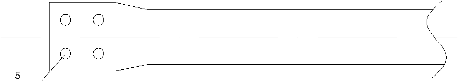
[0029] The insulated tubular busbar with a current of 4000A includes: insulated tubular busbar conductor 1, wire 2, heat dissipation hole 3, heat dissipation space in the tube 4 and end plate opening 5, wherein: the insulated tubular busbar conductor 1 is located on the outermost layer, and the insulation A plurality of wires 2 are arranged inside the tube-shaped bus conductor 1 , and cooling holes 3 are provided at the end of the insulated tube-shaped bus conductor 1 .

[0030] The insulated tubular busbar conductor 1 is specifically a copper tube with an outer diameter of 80 mm and an inner diameter of 60 mm, and the copper content of the copper tube is >99.4%;

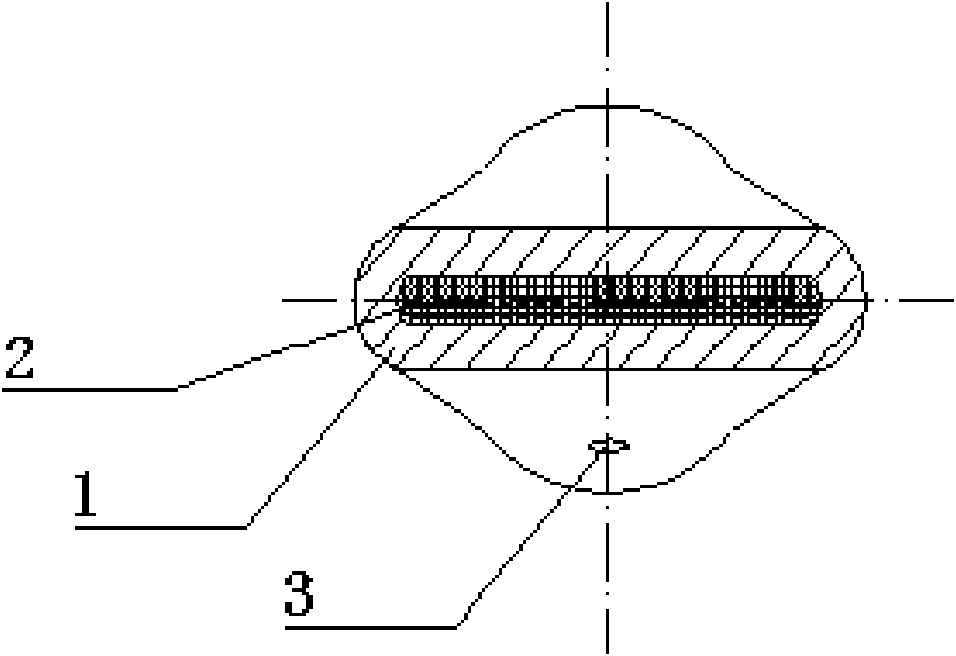
[0031] The wire 2 consists of 300 pieces of 2mm 2 Composed of tinned red copper wire, the end flat pressing effect is shown in Figure 1 side view;

[0032] The cooling hole 3...

Embodiment 2

[0045] As shown in Figure 2, the insulating tubular busbar with a current of 4000A and the processing method of the hollow conductive tube inserted therein,

[0046] The insulating tubular busbar with a current of 4000A includes: insulating tubular busbar conductor 1, inner conductive tube 2, cooling holes 3, heat dissipation space in the tube 4 and end plate opening 5, wherein: insulating tubular busbar conductor 1 is located on the outermost layer, An inner conductive tube 2 is provided inside the insulating tubular bus conductor 1 , and a cooling hole 3 is provided at the end of the insulating tubular bus conductor 1 .

[0047] The insulated tubular busbar conductor 1 is specifically a copper tube with an outer diameter of 80 mm and an inner diameter of 60 mm, and the copper content of the copper tube is >99.4%;

[0048] The inner conductive tube 2 is specifically a copper tube with an outer diameter of 50mm and an inner diameter of 40mm, and the copper content of the coppe...


PUM

PropertyMeasurementUnit
Outer diameteraaaaaaaaaa
The inside diameter ofaaaaaaaaaa
Diameteraaaaaaaaaa

Abstract

The invention relates to an insulating tube type busbar and a manufacturing method thereof in the technical field of high voltage distribution. The insulating tube type busbar comprises: an insulatingtube type busbar conductor, an internal conductive pipe or a plurality of leads, radiating holes, radiating spaces inside the pipe and end plate open pores, wherein the insulating tube type busbar conductor is arranged at the outermost layer and is internally provided with the internal conductive pipe; and the end part of the insulating tube type busbar conductor is provided with the radiating holes. By utilizing the hollow insulating tube type busbar conductor, a conductor is added in the insulating tube type busbar conductor, the hollow conductor of the insulating tube type busbar is internally stuffed with the conductive pipe, or a plurality of corresponding leads and presses the end part thereof into a whole; radiating and temperature reduction measures are taken, and the end part ofthe insulating busbar is provided with radiating holes, therefore, the current-carrying capacity can be increased without increasing the external diameter size of the busbar, thus reducing the using amount of insulation materials and lowering cost.

Description

technical field [0001] The invention relates to an insulated wire in the technical field of high-voltage power distribution and a processing method thereof, in particular to an insulating tubular busbar and a processing method thereof. Background technique [0002] In AC power distribution devices below 35KV, more and more tubular insulated busbars are used to transmit power. The cross-section and diameter of the tubular bus conductor are determined according to the magnitude of the current. Due to the skin effect, the wall thickness of the conductive tube cannot be increased indefinitely. Therefore, under a certain voltage, the larger the current, the larger the diameter of the tubular insulating busbar, and the corresponding increase in insulating materials, and the more supporting accessories. Therefore, even if the voltage is constant, the greater the current, the insulation cost and accessory cost of the tubular insulated busbar will increase greatly, which is obviousl...

Claims


Application Information

Patent Timeline
IPC IPC(8): H01B7/42H01B5/00H01B13/00
Inventor 袁康袁授本
Owner SHANGHAI XIBANG ELECTRIC
Why Eureka
Try Eureka