Supercharge Your Innovation With Domain-Expert AI Agents!

Magnetic head assembly and method of solder bonding

一种接合方法、磁头组件的技术,应用在焊接设备、焊接设备、激光焊接设备等方向,能够解决磁头滑块浮起特性即输出特性变差、滑块姿势变动等问题,达到抑制姿势变化、提高接合可靠性的效果

Active Publication Date: 2010-03-17
TDK CORPARATION
View PDF2 Cites 0 Cited by
  • Summary
  • Abstract
  • Description
  • Claims
  • Application Information

AI Technical Summary

Problems solved by technology

In addition, there is a problem that the posture (inclination angle) of the slider after soldering is greatly changed due to the shrinkage strain generated when the solder ball is solidified.
This posture change degrades the floating characteristic of the head slider, that is, the output characteristic.

Method used


Image

  • Magnetic head assembly and method of solder bonding
  • Magnetic head assembly and method of solder bonding
  • Magnetic head assembly and method of solder bonding

Examples


Embodiment Construction

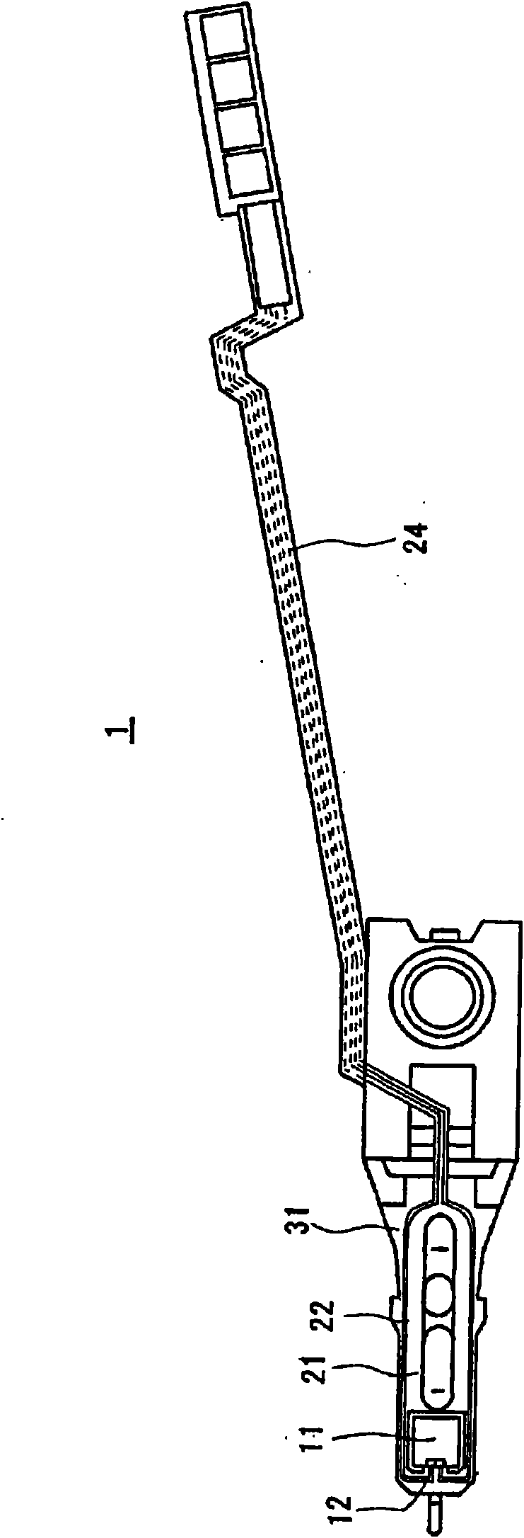
[0035] figure 1 An embodiment of a magnetic head assembly (completed state) for a hard disk drive to which the method of the present invention is applied is shown. The magnetic head assembly 1 includes a slider 11 incorporating a magnetoresistive effect element (magnetic head) 12, and a back surface of the slider 11 bonded by, for example, a thermosetting adhesive, a UV curable adhesive, or a conductive adhesive. flexible part 21.

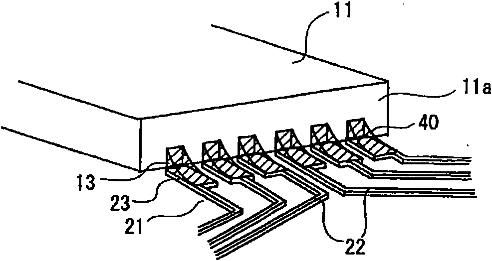
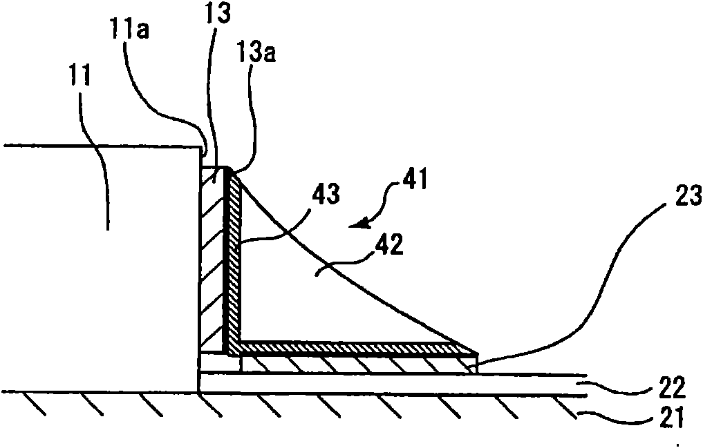
[0036] The flexible member 21 is a leaf spring-like flexible thin metal plate, and is attached to the front end of the load beam in a state where the slider 11 is elastically supported in suspension with respect to the load beam. On the surface of the flexible member 21, a flexible wiring board (FPC) 22 is fixed by pasting an adhesive or the like. The circuit system conduction connection. Flexible wiring substrate 22 such as figure 2 In an enlarged view, after being separated from a plurality of electrode pads 23 arranged on the front end of t...


PUM

PropertyMeasurementUnit
diameteraaaaaaaaaa
diameteraaaaaaaaaa
diameteraaaaaaaaaa

Abstract

A magnetic head assembly and a method of solder bonding are provided to improve the bonding reliablity and inhibit the posture change of the slider. The magnetic head assembly has electrode pads of aslider that have a magnetoresistive element installed therein and electrode pads of a flexible printed circuit that connect the magnetoresistive element to an external circuit are bonded by solder. Inone embodiment, an Au layer is formed on solder contact surfaces of the electrode pads of the slider and the flexible printed circuit, and an AuSn dispersion layer where Au atoms of the Au layer aredispersed is formed at least on the boundary between the solder contact surfaces of the electrode pads and the solder.

Description

[0001] This application is a divisional application of the application dated November 1, 2006, the application number is 200610142910.9, and the title of the invention is a magnetic head assembly and its brazing bonding method. technical field [0002] The present invention relates to a magnetic head assembly in which electrode pads of a slider and electrode pads of a flexible wiring board are joined with Sn solder and a soldering joining method thereof. Background technique [0003] The so-called magnetic head assembly used in hard disk drives (HDD) is composed of a slider assembled with a magnetoresistive effect element and a flexible metal sheet, and has a flexible member elastically supporting the slider, and a flexible member bonded to the surface of the flexible member. A flexible wiring substrate on which the magnetoresistance effect element of the slider is conductively connected with the circuit system of the device on which the magnetic head assembly is installed. ...

Claims


Application Information

Patent Timeline
Patent Type & Authority Applications(China)
IPC IPC(8): B23K1/00B23K26/00B23K101/36G11B21/21
CPCH05K3/3442H01L2224/742H05K2201/10727H05K3/244H05K1/189H05K2203/041G11B5/4853H05K3/3494H05K2203/107Y02P70/50
Inventor 山口巨树灰野孝雄阿部秀昭佐藤俊彦
Owner TDK CORPARATION
Features
  • R&D
  • Intellectual Property
  • Life Sciences
  • Materials
  • Tech Scout
  • Unparalleled Data Quality
  • Higher Quality Content
  • 60% Fewer Hallucinations
Learn More