Bionic mechanical eyeball

A technology of bionic machinery and eyeballs, applied in the field of robotics, achieves fast response, high positioning accuracy, and saves installation space

Inactive Publication Date: 2010-03-17
南通爱利特机电制造有限公司
View PDF0 Cites 23 Cited by
  • Summary
  • Abstract
  • Description
  • Claims
  • Application Information

AI Technical Summary

Problems solved by technology

The camera is installed in the center of the sphere

Method used


Image

  • Bionic mechanical eyeball
  • Bionic mechanical eyeball
  • Bionic mechanical eyeball

Examples


Embodiment Construction

[0031] A preferred embodiment of the present invention will be further described below in conjunction with the accompanying drawings.

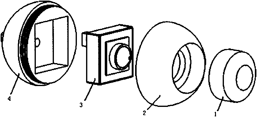
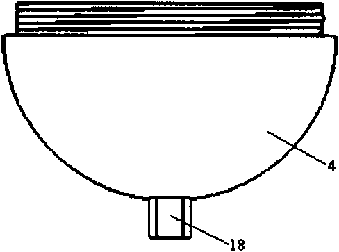
[0032] figure 1 is the structure of the eyeball (17). The eyeball (11) is divided into two halves, the CCD camera (3) is placed in the middle, and the two hemispherical shells (2, 4) are connected by threads. Eyeball front cover (1) is for attractive in appearance. The effect of the boss (18) on the rear hemispherical shell (4) is to make eyeballs rotate. Holes are punched on the rear hemispherical shell (4) of the eyeball, which is convenient for the data line of the CCD camera (3) to be connected to the control part at the back of the bionic eye.

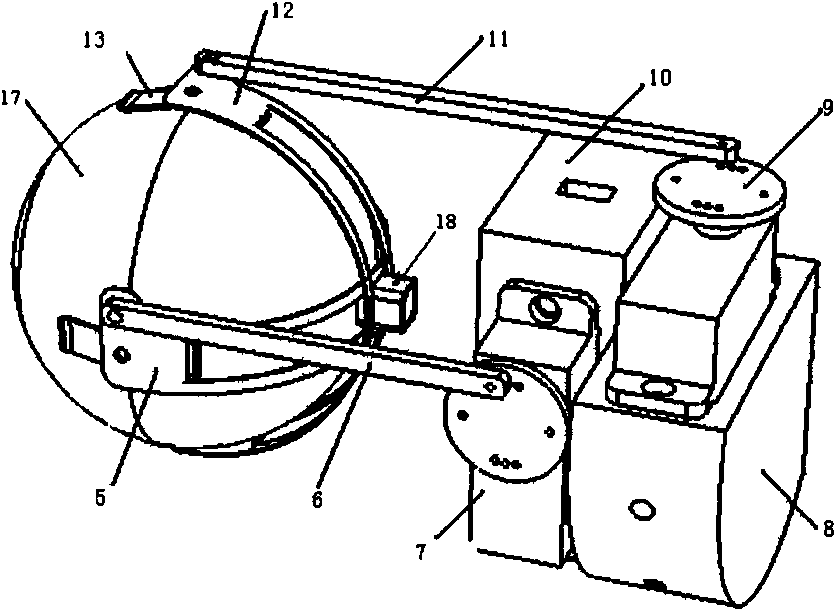
[0033] In order to enable the eyeball to rotate three-dimensionally, the Figure 6 Shown support sheet (13) supports eyeball. Such as Figure 5 As shown, the four supports are evenly arranged in the horizontal and vertical directions of the eyeball surface, and just straddle the connecting s...


PUM


Abstract

The invention relates to a bionic mechanical eyeball comprising an eyeball and a cylindrical casing, wherein an inner cavity of the eyeball is provided with a CCD camera, and two steering engines arerespectively installed in the inner cavity at the back part of the cylindrical casing by a steering engine installation rack and respectively drive the eyeball to carry out right-and-left and up-and-down transmission by a transmission mechanism. The invention has three freedom degrees and realizes the simulation of the movement of single eye of a person basically. The visual angle of the mechanical eyeball reaches 40 degrees, and the control accuracy is 0.5 degrees. The invention has compact structure and high control accuracy.

Description

technical field [0001] The invention relates to robot technology, in particular to a bionic mechanical eyeball. Background technique [0002] In science fiction, the potential of robots is infinitely expanded. They can make eye contact with humans, make physical contact, and can automatically adapt to the external environment. They are smarter, smarter, and even surpass humans. We know that the eyes are the window of perception, and more than 90% of the information is obtained by vision. If robots could have the same eyes as humans, intelligent robots would no longer be the glamorous plot of science fiction stories. [0003] In fact, whether an "artificial eye" can be created so that robots can read and read like humans has always been an important topic of intelligent automation. In life, the scope of application of robots with vision functions is far greater than this. Bionic mechanical eyeballs can be used for automatic monitoring, eyes of intelligent robots, target tr...

Claims


Application Information

Patent Timeline
Patent Type & Authority Applications(China)
IPC IPC(8): B25J19/00
Inventor 李磊李庆梅谢少荣罗均李恒宇
Owner 南通爱利特机电制造有限公司
Why Eureka
Try Eureka