Front suspension frame for double-body vehicle

A technology of front suspension and catamaran, which is applied in the field of front suspension and suspension of catamaran, which can solve the problems of unsightly appearance, inconvenient loading and unloading of wheels, difficulty in satisfying convenient disassembly, etc., and achieve novel appearance and high practicability , the effect of compact structure

Active Publication Date: 2010-03-17
ZHEJIANG GEELY AUTOMOBILE RES INST CO LTD +1
0 Cites 9 Cited by

AI-Extracted Technical Summary

Problems solved by technology

The existing ordinary motorcycle suspension is usually a front fork type. Although it has a simple structure, it will cause suspension structures on both sides of the wheel, which is not convenient for loading and unloading of the wheel, and is not beautiful
Howev...

Abstract

The invention provides a front suspension frame for a double-body vehicle, belonging to the field of mechanical technology. The front suspension frame solves the problem that the existing front suspension frame can not meet the requirement for the driving stability of the double-body vehicle. In the front suspension frame for the double-body vehicle, the double-body vehicle is formed by combininga left single-body vehicle and a right single-body vehicle which can respectively run independently and are respectively provided with a front wheel and a rear wheel. The front suspension frame is arranged between the front wheels of the bodyworks of the single-body vehicles, and comprises steering knuckles arranged at one end of the front wheels, a swing arm and a buffer gear, wherein the lower ends of the steering knuckles are connected with wheel hubs of the front wheels; the steering knuckles can drive the front wheels to turn when turning; the upper ends of the steering knuckles are articulated with a bodywork; one end of the swing arm is articulated with the lower ends of the steering knuckles, and other end thereof is articulated with the bodywork; and the buffer gear is connected between the bodywork and the swing arm. The front suspension frame for the double-body vehicle has compact and simple structure, more novel appearance and higher practicality.

Application Domain

Technology Topic

Image

  • Front suspension frame for double-body vehicle
  • Front suspension frame for double-body vehicle

Examples

  • Experimental program(1)

Example Embodiment

[0034] A catamaran consists of two monocoques that can run independently and have a front wheel and a rear wheel. The front suspension system has two mutually symmetrical front suspensions, that is, a left front suspension and a right front suspension. The left front suspension is arranged between the body of the left monobody and the front wheel and is located on the right side of the front wheel, and the right front suspension is arranged between the body of the right monobody and the front wheel and is located on the right side of the front wheel. The front wheel is on the left side.
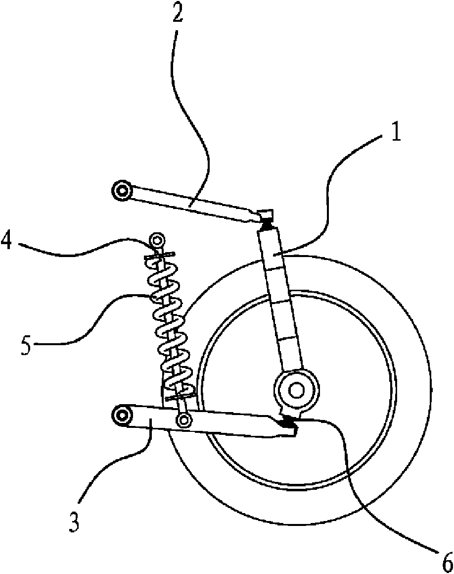
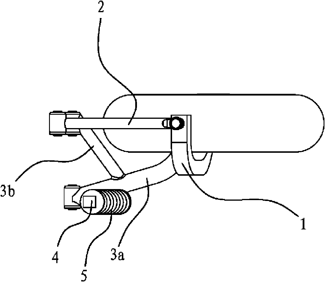
[0035] like figure 1 and figure 2 As shown, the front suspension for the catamaran is arranged between the body and the front wheels of the catamaran. It includes a steering knuckle 1, a swing arm and a buffer mechanism, and the steering knuckle 1, the swing arm and the buffer mechanism are all arranged on one side of the front wheel.
[0036] The steering knuckle 1 is rigidly connected to the wheel hub. One end of the swing arm is hinged with the steering knuckle 1, and the other end of the swing arm is connected with the rotating shaft of the vehicle body.
[0037] The buffer mechanism is connected between the vehicle body and the swing arm. There are two swing arms: upper swing arm 2 and lower swing arm 3. One end of the upper swing arm 2 is hinged with the upper end of the steering knuckle 1, the other end of the upper swing arm 2 is connected with the rotating shaft of the vehicle body, one end of the lower swing arm 3 is hinged with the steering knuckle, and the other end of the lower swing arm 3 is connected with the rotating shaft of the vehicle body. In the embodiment, the buffer mechanism is connected between the vehicle body and the lower swing arm 3 , the upper end of the buffer mechanism is hinged to the vehicle body, and the lower end is hinged to the middle of the lower swing arm 3 .
[0038] The buffer mechanism includes a shock absorber 4 and a coil spring 5, the upper end of the shock absorber 4 is hinged with the vehicle body, the lower end of the shock absorber 4 is hinged with the middle part of the lower swing arm 3, the above-mentioned coil spring 5 is sleeved on the shock absorber 4 and The two ends act on the two ends of the shock absorber 4 respectively.
[0039] The lower end of the steering knuckle 1 bends and extends to the longitudinal center plane of the front wheel, and the upper end of the steering knuckle 1 bends and extends above the front wheel and is located at the longitudinal center plane of the front wheel.
[0040] The lower swing arm 3 includes a main arm 3a and a support arm 3b. One end of the support arm 3b is fixedly connected to the middle part of the main arm 3a, and the other end of the support arm 3b extends obliquely to the longitudinal center plane of the front wheel and is located behind the front wheel. Both the main arm 3a and the support arm 3b are hinged with the vehicle body, and the connecting ends of the main arm 3a, the support arm 3b and the vehicle body are located on the same rotation axis. In this embodiment, the upper swing arm 2 is located on the longitudinal center plane of the front wheel, and the upper swing arm 2 and the lower swing arm 3 are arranged in parallel, and the shock absorber 4 and the steering knuckle 6 are arranged in parallel.
[0041] In addition, the hinge point between the upper end of the steering knuckle 6 and the upper swing arm 2 is located behind the hinge point between the lower end of the steering knuckle 6 and the rotating shaft of the front wheel.
[0042] In the catamaran with this front suspension, the swing arm 2 and the lower swing arm 3 guide the wheels, the coil spring 5 supports the vehicle body and relieves impact, and the shock absorber 4 absorbs vibration. Of course, the main arm 3a and the support arm 3b of the lower swing arm 3 effectively increase the lateral stiffness of the suspension.

PUM

no PUM

Description & Claims & Application Information

We can also present the details of the Description, Claims and Application information to help users get a comprehensive understanding of the technical details of the patent, such as background art, summary of invention, brief description of drawings, description of embodiments, and other original content. On the other hand, users can also determine the specific scope of protection of the technology through the list of claims; as well as understand the changes in the life cycle of the technology with the presentation of the patent timeline. Login to view more.

Similar technology patents

Mounting frame for fuel cell stack

Owner:SHANGHAI SHENLI TECH CO LTD

Punching robot production control system

Owner:SICHUAN CHANGHONG ELECTRIC CO LTD

Classification and recommendation of technical efficacy words

  • Easy to maintain
  • Compact structure
Why Eureka
Try Eureka