

P step actuating mechanism of electric control mechanical automatic variable-speed device for electrically-operated car and control system
A technology of automatic transmission and actuator, applied in the field of automobile safety system, can solve the problems of inability to lock the wheels, unfavorable driving safety, unreliable parking, etc., and achieve the effects of good braking effect, convenient use and increased reliability.
- Summary
- Abstract
- Description
- Claims
- Application Information
AI Technical Summary
Problems solved by technology
Method used
Image

Examples
Embodiment Construction
[0041] In order to understand the technical content of the present invention more clearly, the following examples are given in detail.
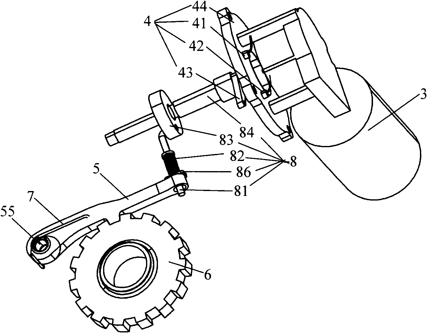
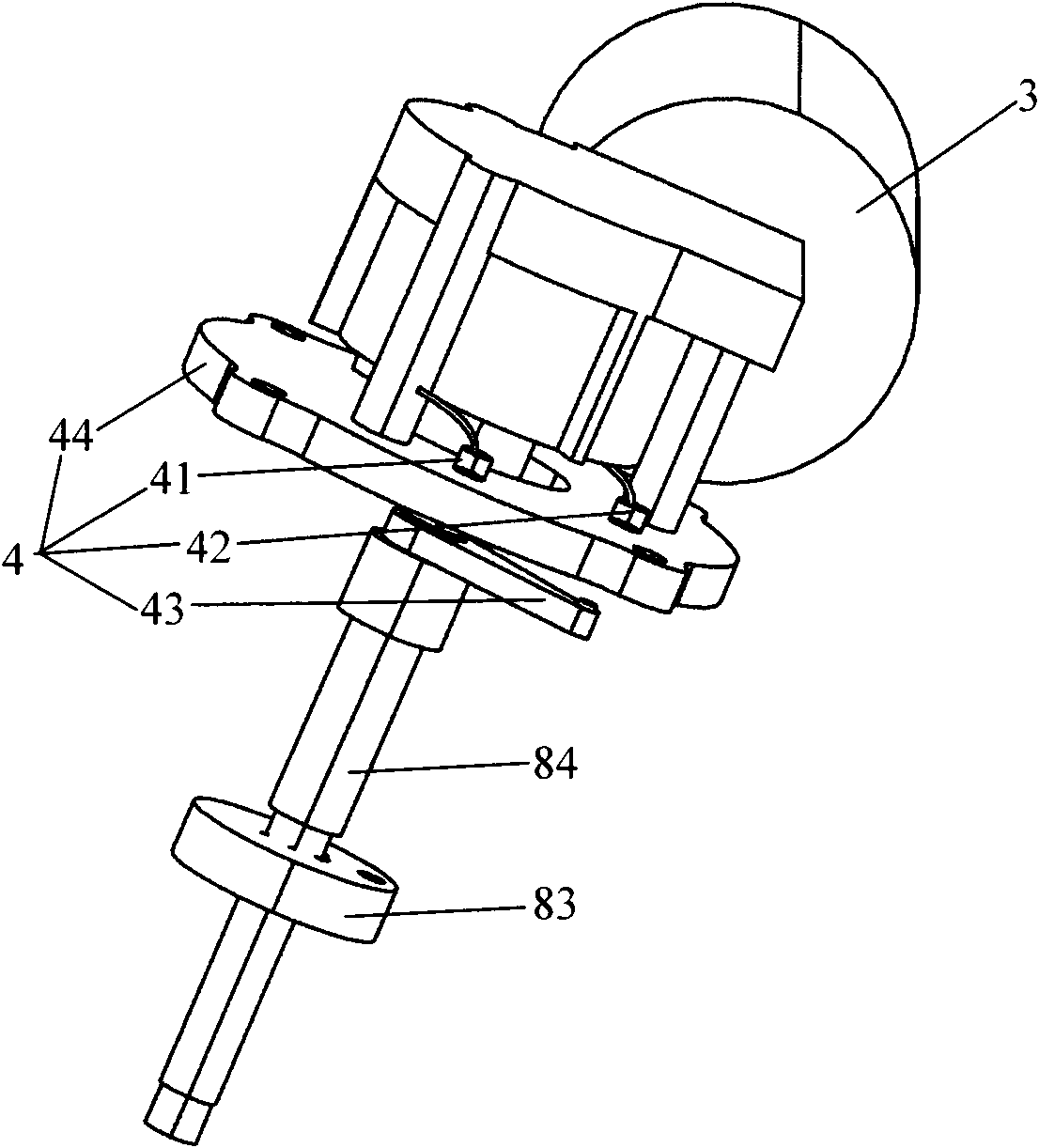
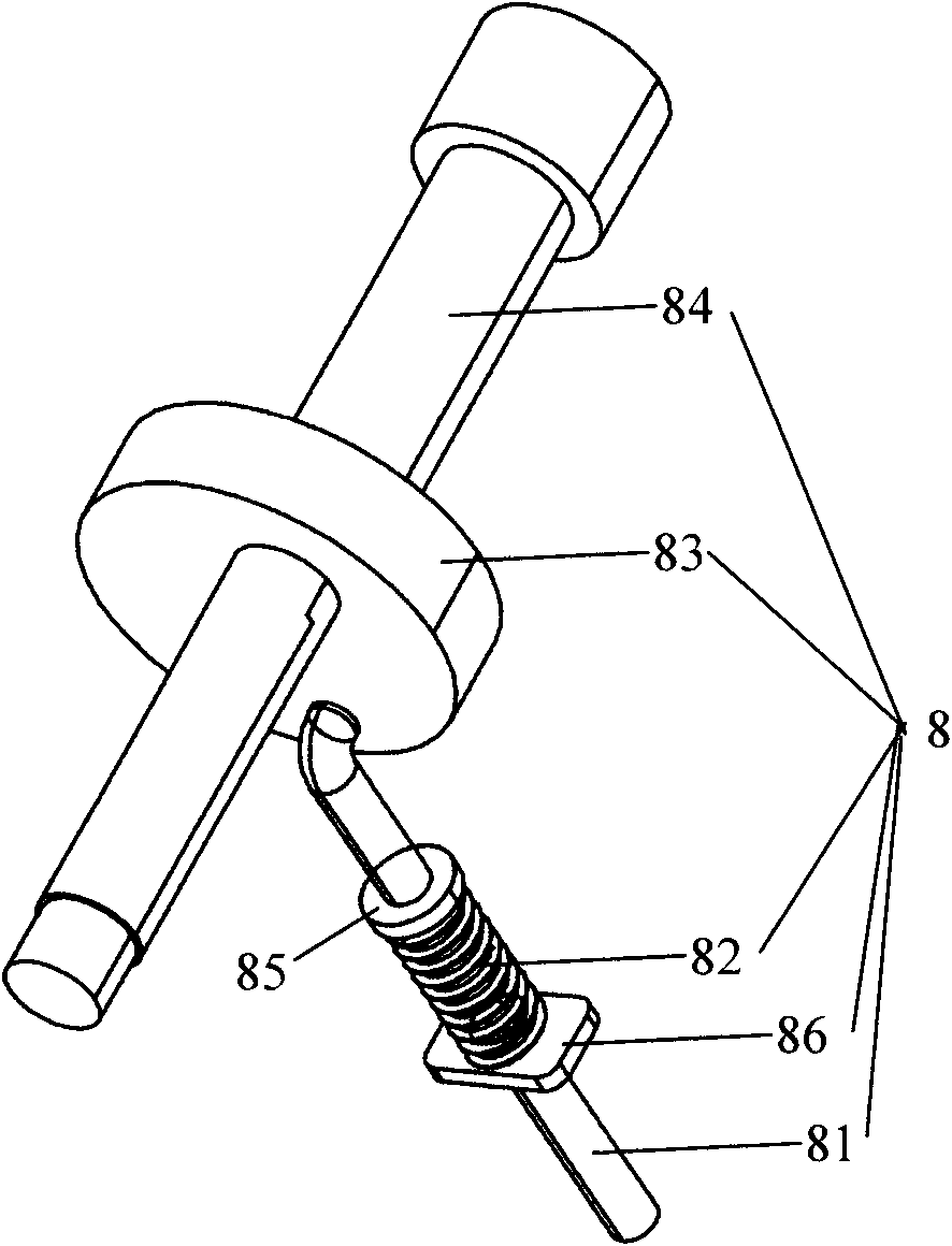
[0042] see Figure 1 to Figure 7As shown, the electric vehicle electronically controlled mechanical automatic transmission P file actuator and control system of the present invention include a shift handle P file position detection device 1, a P file electronic control device 2, a drive device 3, a drive device position detection device 4, Pawl 5 and ratchet 6, the P gear electronic control device 2 is electrically connected with the shift handle P gear position detection device 1, the drive device 3 and the drive device position detection device 4 respectively, and the drive device The position detecting device 4 and the driving device 3 are cooperatingly arranged to detect the rotational position of the drive shaft of the driving device 3, and the driving device 3, the ratchet 5 and the ratchet 6 are cooperatingly arranged so that the drivi...
PUM
 Abstract
Description
Claims
Application Information