
Navigation device

A navigation device and receiving device technology, applied in navigation, surveying devices, surveying and navigation, etc., to achieve the effects of improving positioning accuracy, improving flexibility, and improving convenience

Inactive Publication Date: 2010-03-17
VICTOR CO OF JAPAN LTD +1
View PDF0 Cites 8 Cited by
  • Summary
  • Abstract
  • Description
  • Claims
  • Application Information

AI Technical Summary

Problems solved by technology

That said, positioning leaves room for improvement in terms of being limited to the use of three detectors

Method used


Image

  • Navigation device
  • Navigation device
  • Navigation device

Examples


Embodiment 1

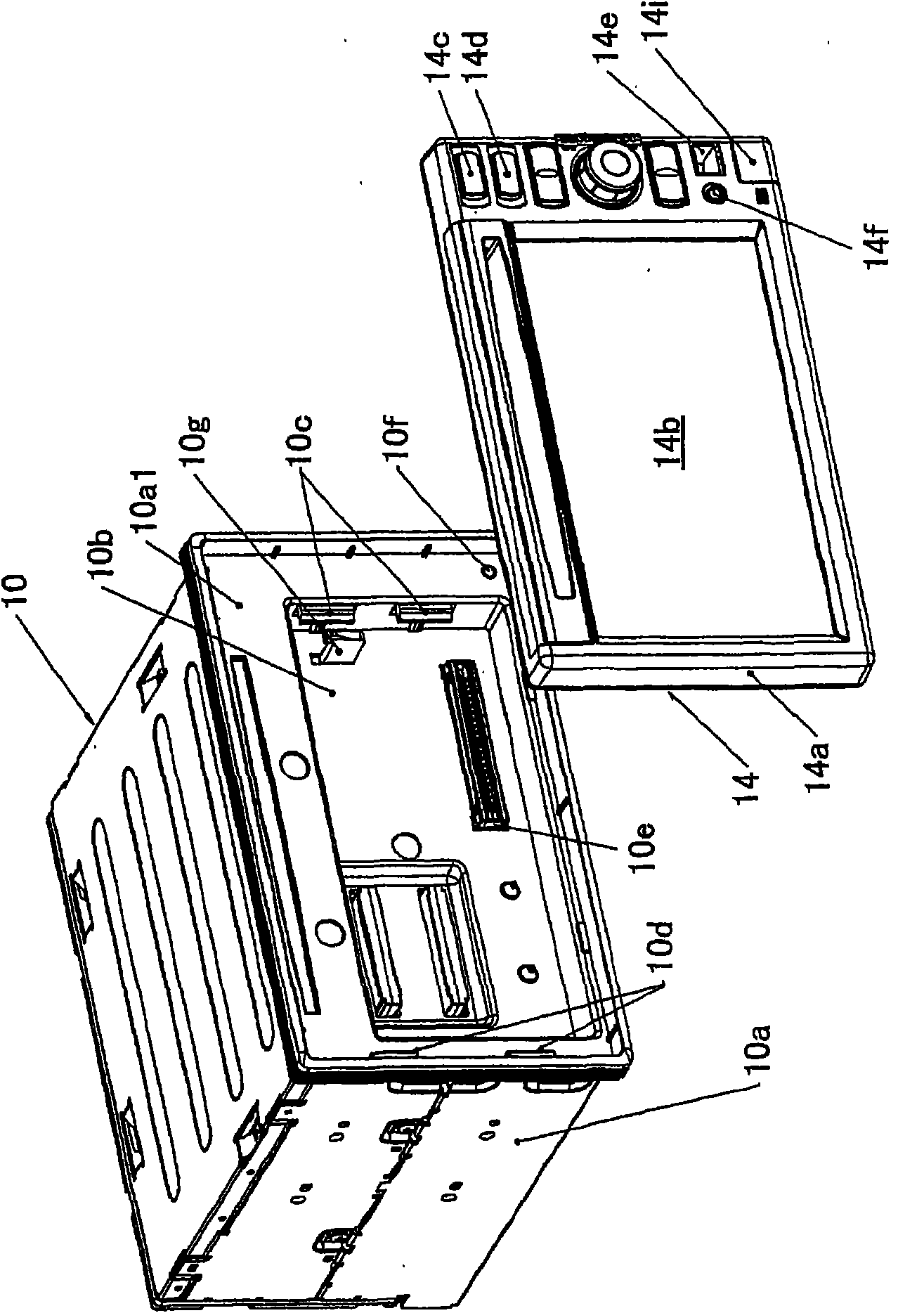
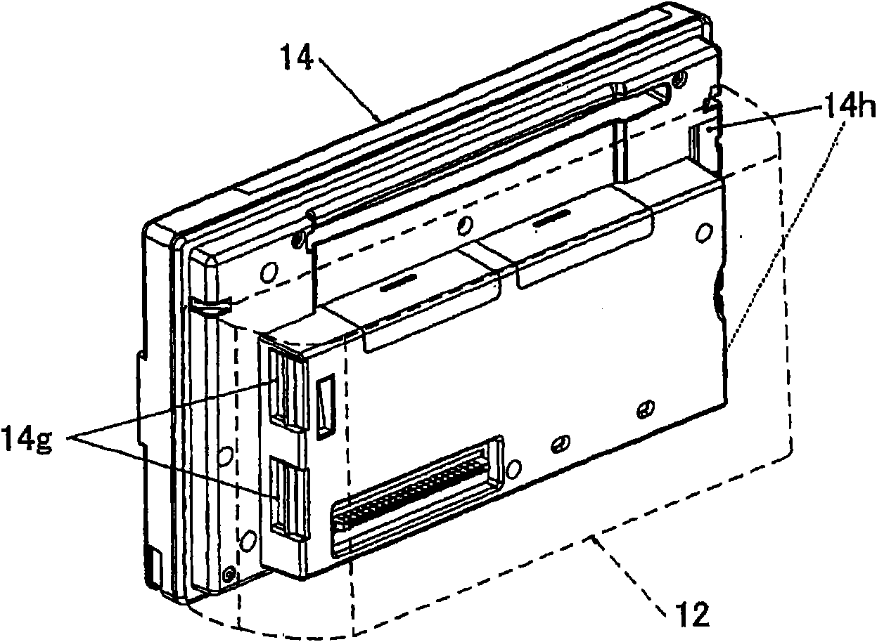
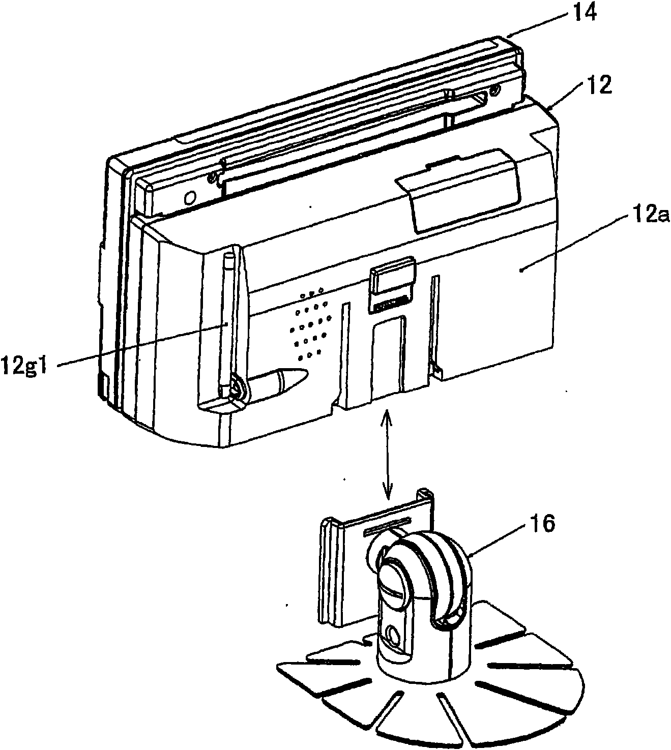
[0062] figure 1 It is a perspective view of the front side of the base unit and the front panel unit in the navigation device according to the first embodiment of the present invention, figure 2 is a perspective view of the rear side of the front panel unit, image 3 It is a perspective view of the front panel unit (rear side), the bracket unit, and the bracket unit mounting arm. Figure 4 An explanatory diagram showing the state in which these units are mounted, Figure 5 (a) is an explanatory diagram of the vicinity of the driver's seat of the vehicle, Figure 5 (b) is an explanatory diagram of the vicinity of the steering wheel.

[0063] As shown in the figure, the navigation device according to the embodiment of the present invention is equipped with: a basic unit 10, which is fixed or built (fixed freely) on the instrument panel of the vehicle A, and is provided with operating power from the power supply (battery) of the vehicle A; Unit 12, which is fixed (fixed free...

Embodiment 2

[0238] Figure 30 Indicates the operation of the navigation device according to the second embodiment of the present invention, and Figure 10 The flow chart of the same flow chart. Illustrated processing is also the same as Figure 10 It is also executed by the navigation microcomputer 14m.

[0239] In the following description, the illustrated process starts when the user operates the sensor mode switching screen appropriately displayed on the touch panel 14s disposed on the liquid crystal panel 14b, that is, presses the touch panel 14s. In S900, According to the touch panel operation, a sensor mode switching screen is displayed to urge the user to select.

[0240] Next, proceed to S902 to determine whether the user has selected the single sensor mode, or in other words whether to give an external instruction about the detector that should be used for vehicle A's position positioning, and if yes, proceed to S904 to determine the single sensor mode Estimate the position o...


PUM


Abstract

A navigation device has a base unit (10) that can be fixed to a vehicle and a front panel unit (14) that can be detachably attached to the base unit. The navigation device further has at least three sensors that are a receiver (20) for receiving a GPS signal, a wheel speed sensor (22) for detecting wheel speed, and a gyro sensor (24) for detecting angular velocity about the gravity axis. A microcomputer of the front panel unit determines, in a way corresponding to output conditions of the sensors, a sensor that is to be used for locating the position of the vehicle. Because a sensor to be usedfor locating a vehicle position is optimally selected and determined corresponding to output conditions of the sensors, the accuracy of locating a vehicle position is enhanced and the sensors can bemore flexibly used in such position locating because position locating is not necessarily confined to the use of the three sensors.

Description

technical field [0001] The present invention relates to a navigation device, and more specifically relates to a device mounted on a vehicle to transmit information (direction, map, route, etc.) for a driver to reach a destination. Background technique [0002] As mentioned above, the navigation device was originally limited to the type that was integrally fixed to the vehicle, but recently a portable type that can be moved has also been proposed, and furthermore, a detachable type that allows only a part of the navigation function to be detached has been proposed, and the convenience of usability is further improved. type navigation device (see, for example, Patent Document 1). [0003] The technology described in Patent Document 1 is a navigation device, which is composed of a vehicle signal processing circuit including a GPS receiver connected to a GPS antenna, a rotation sensor and a vehicle speed signal, a display for displaying a map, and an ECU for overall control; Eq...

Claims


Application Information

Patent Timeline
Patent Type & Authority Applications(China)
IPC IPC(8): G01C21/00G08G1/0969B60R1/00G09B29/00B60R11/02G09B29/10G01S5/14G01C21/26G01C21/28G01S19/42
CPCG01C21/165B60R11/0258G01C21/3688B60R11/0235B60R2011/0078G01C21/26G01C21/265G01C21/28B60R2011/0073G01S19/42
Inventor 德江纯山本和广增田浩朗大石康夫
Owner VICTOR CO OF JAPAN LTD
Learn More