Positioning jig of hole system welding platform

A welding platform and positioning fixture technology, which is applied in the field of positioning and clamping of workpieces on welding workbenches, can solve the problems of high cost of positioning parts, vertical deviation of the insertion rod, and affecting positioning accuracy, etc.

Inactive Publication Date: 2010-03-24
VALTRA (SHANGHAI) MASCH CO LTD
View PDF10 Cites 5 Cited by
  • Summary
  • Abstract
  • Description
  • Claims
  • Application Information

AI Technical Summary

Problems solved by technology

[0002] The flexible welding workbench combined with holes or slot holes has many evenly arranged positioning holes on its table, and these positioning holes are used to locate or connect the corresponding fixtures or auxiliary tools, so as to realize the reasonable positioning of the workpieces welded on the platform. Positioning and clamping: There are mainly two positioning methods utilizing positioning holes in the prior art, and a commonly used one is the positioning method disclosed in the invention application of CN101053933A and the patent No. US5,676,359. Such positioning methods mostly use the superposition and combination of welding square boxes, right-angle positioning parts, connectors, etc. to complete the spatial positioning of the welded workpieces. This positioning method can usually com

Method used


Image

  • Positioning jig of hole system welding platform
  • Positioning jig of hole system welding platform
  • Positioning jig of hole system welding platform

Examples


Embodiment Construction

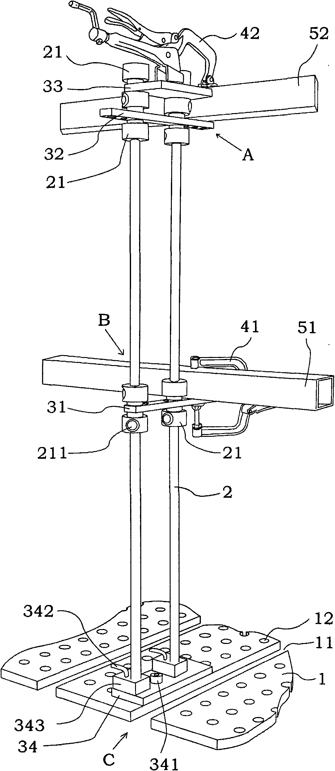
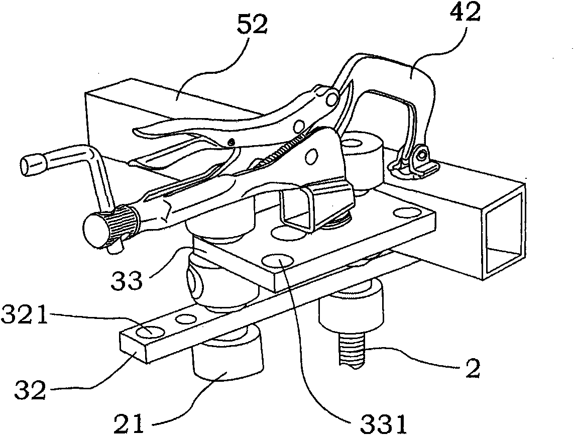
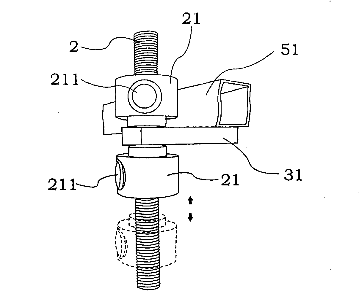
[0019] like Figure 1 to Figure 3 The slots shown are combined with the positioning fixture of the welding workbench. There are positioning grooves 11 between the adjacent strip-type welding worktops 1 of the workbench. Cylindrical positioning holes 12 are evenly opened on the welding worktop 1. Through the locking pin 341 , the connecting plate 34 is fixed on the table top 1, two positioning blocks 343 are arranged on the connecting plate 34, and a half nut is respectively arranged inside each positioning block 343, and the inner screw hole formed by the half nut is just in line with the welding table 1 Corresponding to the corresponding positioning hole 12 on the top, insert the two screw rods 2 into the inner screw holes and lock them through the locking handle 342; an appropriate number of fast forward and backward nuts are screwed on each screw rod 2, and the fast forward and backward nuts have A nut sleeve 21 and a fast forward and backward button 211, the surface of the...


PUM


Abstract

The present invention relates to a positioning jig of a hole system welding platform, which comprises more than one positioning support rod, the positioning support rod is suitable for passing througha positioning hole of the hole system welding platform and extending positioning along two sides of the positioning hole, more than one of the positioning support rod is used as support for forming at least one positioning support surface or clamping surface. The positioning support surface or support platform formed by building the support bar can replace a square-box function in prior art. Thesupport rod can extend along two sides of the positioning hole, thereby, a height of the formed support surface or support platform can be adjusted. Compared with the clamping by utilizing an insert type clamp in prior art, the formed support surface is more stable and accurate by selecting more than one positioning support bar, which realizes the support function no existed in the insert type clamp.

Description

technical field [0001] The invention relates to a welding positioning fixture, which is especially suitable for positioning and clamping workpieces on a welding workbench combined with holes or slots. Background technique [0002] The flexible welding workbench combined with holes or slot holes has many evenly arranged positioning holes on its table, and these positioning holes are used to locate or connect the corresponding fixtures or auxiliary tools, so as to realize the reasonable positioning of the workpieces welded on the platform. Positioning and clamping: There are mainly two positioning methods utilizing positioning holes in the prior art, and a commonly used one is the positioning method disclosed in the invention application of CN101053933A and the patent No. US5,676,359. Such positioning methods mostly use the superposition and combination of welding square boxes, right-angle positioning parts, connectors, etc. to complete the spatial positioning of the welded wo...

Claims


Application Information

Patent Timeline
IPC IPC(8): B23K37/04B23K37/053
Inventor 王汉义
Owner VALTRA (SHANGHAI) MASCH CO LTD
Why Eureka
Try Eureka