Method and device for fired intermediate overheating during direct solar vapourisation in a solar thermal power station

A technology of solar energy and thermal power plants, applied in the field of solar thermal power plant equipment, can solve problems such as pressure loss and inappropriateness, and achieve the effects of high process temperature, high concentration effect, and high process maturity

Inactive Publication Date: 2010-03-24
SIEMENS AG
View PDF0 Cites 8 Cited by
  • Summary
  • Abstract
  • Description
  • Claims
  • Application Information

AI Technical Summary

Problems solved by technology

However, this form of intermediate reheating does not appear to be suitable, since the intermediate reheating in solar collectors would result in high pressure losses

Method used


Image

  • Method and device for fired intermediate overheating during direct solar vapourisation in a solar thermal power station
  • Method and device for fired intermediate overheating during direct solar vapourisation in a solar thermal power station
  • Method and device for fired intermediate overheating during direct solar vapourisation in a solar thermal power station

Examples


Embodiment Construction

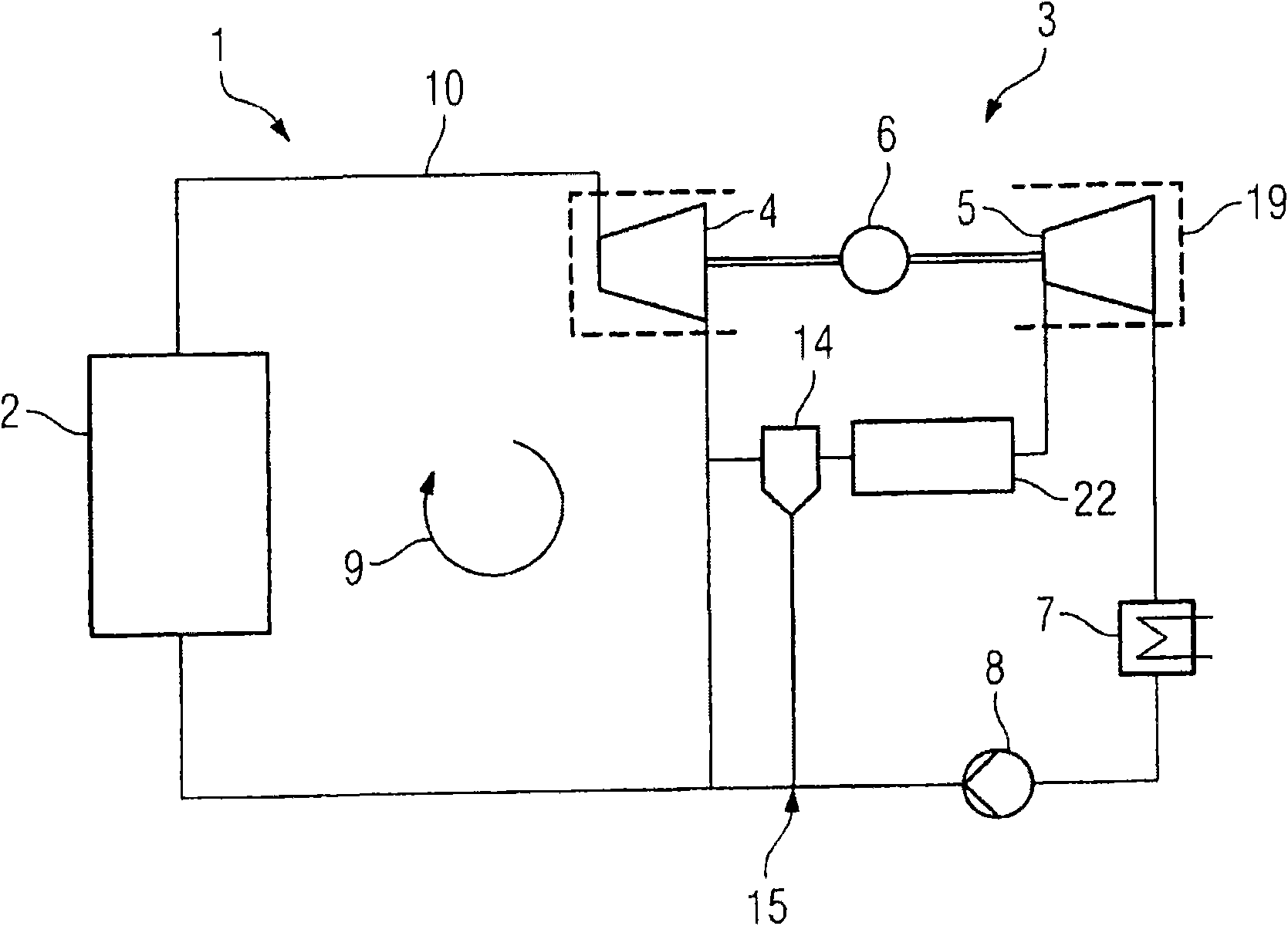
[0036] figure 1 The structure and cycle of a solar thermal power plant 1 with direct vaporization according to the invention are schematically shown. The plant 1 comprises a solar harvesting field 2 in which sunlight is collected and converted into heat energy and may for example have parabolic trough collectors, solar towers or Fresnel collectors. The collected sunlight is delivered to the heat transfer medium, which is vaporized and introduced as a working fluid through the live steam line 10 into the expansion section 19 consisting of the steam turbine 3 , for example. The steam turbine 3 includes a high-pressure turbine 4 and a low-pressure turbine 5 , which drive a generator 6 . The working fluid is expanded in the steam turbine 3 and subsequently liquefied in the condenser 7 . The feed water pump 8 pumps the liquefied heat transfer medium back to the solar collection field 2 , thus closing the heat transfer medium or working fluid circuit 9 .

[0037] according to fi...


PUM


Abstract

The invention relates to a solar thermal power station (1) comprising a work fluid circuit (9), a solar steam generator based on direct vapourisation and a steam turbine (3) for releasing the work fluid for technical work. The solar steam generator and the steam turbine (3) are mounted in the work fluid circuit (9). The solar thermal power station comprises an additional firing system (22) for intermediate heating of the work fluid. The invention also relates to a method for operating said type of installation.

Description

technical field [0001] The invention relates to a method for operating a solar thermal power plant and a solar thermal power plant comprising a solar boiler based on direct vaporization and an intermediate reheater for combustion of a working fluid. Background technique [0002] Solar thermal power plant is another kind of power generation device that is different from traditional ones. Solar thermal plants use the sun's radiant energy to produce electricity. It consists of a solar power plant section for absorbing solar energy and a second mostly conventional power plant section. [0003] A solar power plant partly includes a solar harvesting field, that is to say a concentration system including collectors. The concentrating collector is the main component of the solar power plant section. Known collectors here are parabolic trough collectors, Fresnel collectors, solar pylons and parabolic mirrors. Parabolic trough collectors concentrate sunlight on absorber tubes posi...

Claims


Application Information

Patent Timeline
Patent Type & Authority Applications(China)
IPC IPC(8): F22B1/00F03G6/00F01K7/22F01K3/26F01K3/18F22G1/12F03G6/06
CPCY02E10/46F22G1/12F22B1/006F22B1/003F03G6/003F01K7/22F01K3/188F01K7/223
Inventor 于尔根·伯恩鲍姆马库斯·菲克特纳乔格·哈伯伯格格哈德·齐默尔曼
Owner SIEMENS AG
Why Eureka
Try Eureka