Combined ventilator/gas valve unit

A ventilator and gas valve technology, applied in the field of gas heating equipment, can solve the problems of long tolerance chain, poor reliability, high cost, etc.

Inactive Publication Date: 2012-11-14
斯博德累斯顿有限公司
View PDF5 Cites 0 Cited by
  • Summary
  • Abstract
  • Description
  • Claims
  • Application Information

AI Technical Summary

Problems solved by technology

[0007] Furthermore, due to the large number of components required, the tolerance chain is very long, which makes the reliability of standard gas heating equipment less reliable given the durability
Furthermore, the large number of components requires a large number of manufacturing steps, thus resulting in high costs

Method used


Image

  • Combined ventilator/gas valve unit
  • Combined ventilator/gas valve unit
  • Combined ventilator/gas valve unit

Examples


Embodiment Construction

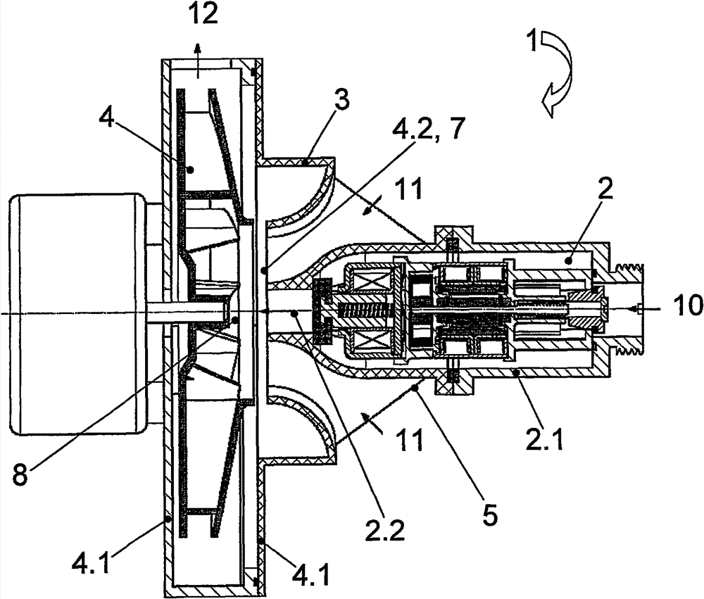
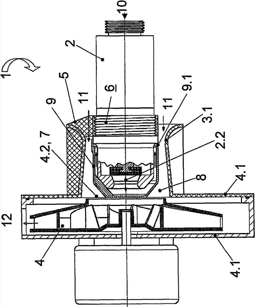
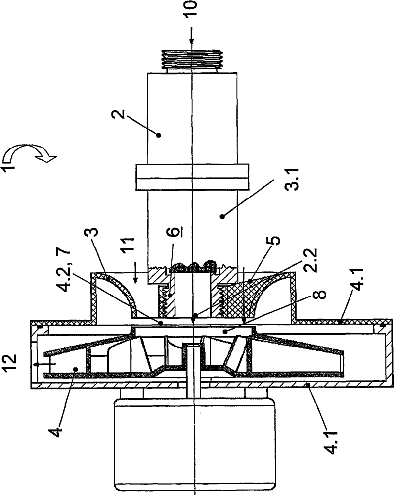
[0035] figure 1 A sectional view of a combined fan / air valve device 1 is illustrated with the suction side 4 . 2 of the fan housing 4 . 1 formed as a nozzle 3 and the fin 5 . The combined fan / air valve device 1 essentially comprises an air valve 2 with a housing 2.1, a nozzle 3 arranged behind the air valve 2 and an adjoining fan 4 formed as a radial fan with multipart ventilation Chassis 4.1. This embodiment of the invention is characterized in that the suction side 4.2 of the fan housing 4.1 is formed as a nozzle 3 to which the gas valve 2 is fixed by means of a fin 5 extending between the nozzle 3 and the housing 2.1 of the valve 2 3. The suction side 4.2 of the fan housing 4.1 is formed as a cover, which can fit into a complementary second housing 4.1 formed in the shape of a pot. The air valve 2 is arranged concentrically in the air inflow channel 7 of the fan 4 . While the gas 10 passes axially through the gas valve 2 , the air 11 is sucked in through the nozzle 3 ex...


PUM


Abstract

Disclosed is a combined ventilator / gas valve unit (1) comprising at least one gas valve (2) that is disposed in a housing (2.1), a nozzle (3) located therebehind, and an adjoining ventilator (4) which is provided with a multipart ventilator housing (4.1). According to the invention, the suction side (4.2) of the ventilator housing (4.1) is designed as a nozzle (3) to which the gas valve (2) is fastened.

Description

technical field [0001] The present invention relates to a combined ventilator / gas valve device for use in a burner of an adjustable gas heating installation, said device for adapting to varying heat loads and for abruptly shutting off the flow of fuel gas, especially for use in domestic spaces Gas heating for heating and hot water supply. Background technique [0002] Against the backdrop of limited fossil fuel resources, high-efficiency, low-emission gas-fired heating installations are considered to be of great importance in the future in order to avoid human-limiting climate change in almost all regions. For example, optimum combustion, ie achieving the desired lambda value, ensures low emission values ​​and high efficiency of the combustion plant. [0003] The desired lambda value is technically achieved by controlling the air / gas mixture ratio, usually with a pneumatic interconnection, that is, by pneumatically controlling the gas valve according to the air volume flow ...

Claims


Application Information

Patent Timeline
Patent Type & Authority Patents(China)
IPC IPC(8): F23D14/36F23D14/60F23D14/64F23L5/02
CPCF23D14/60F23L5/02F23D14/64F23D14/36
Inventor T·罗施基J·克勒M·加莫
Owner 斯博德累斯顿有限公司
Why Eureka
Try Eureka