Optical head device and optical disc device

A technology for optical head devices and optical discs, which is applied to optical recording heads, beam guiding devices, optical detectors, etc., can solve problems such as the complexity of the optical head device structure, improve reliability, and reduce the impact of push-pull signals Effect

Active Publication Date: 2010-03-24
MITSUBISHI ELECTRIC CORP
View PDF2 Cites 2 Cited by
  • Summary
  • Abstract
  • Description
  • Claims
  • Application Information

AI Technical Summary

Problems solved by technology

However, there is a problem that the structure of the optical head device is complicated by adding a photosensitive element and an arithmetic circuit for such countermeasures.

Method used


Image

  • Optical head device and optical disc device
  • Optical head device and optical disc device
  • Optical head device and optical disc device

Examples


Embodiment approach 2

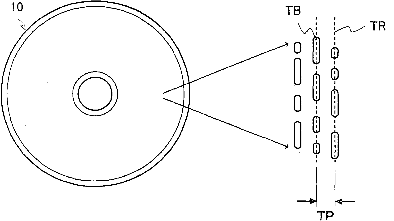
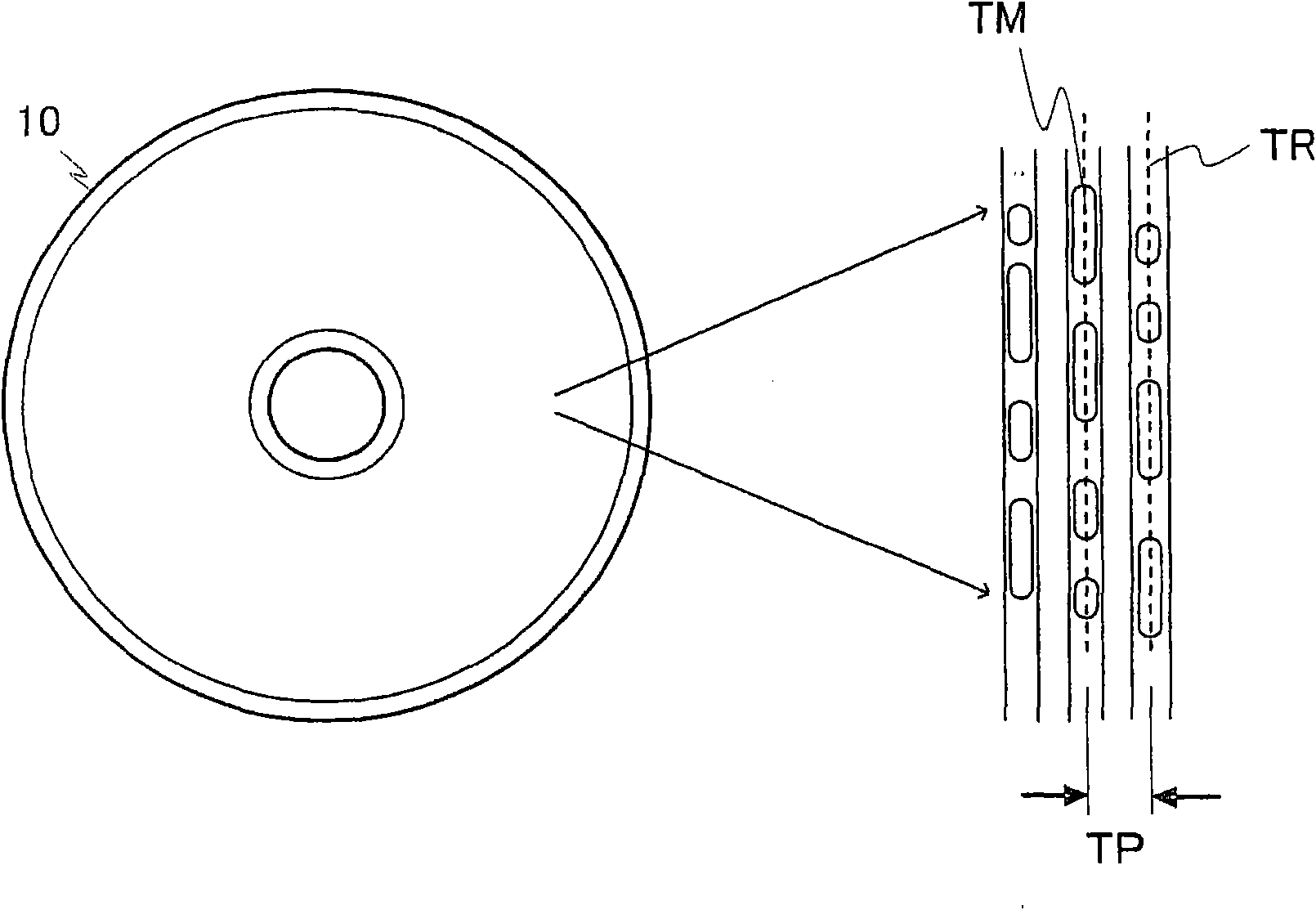
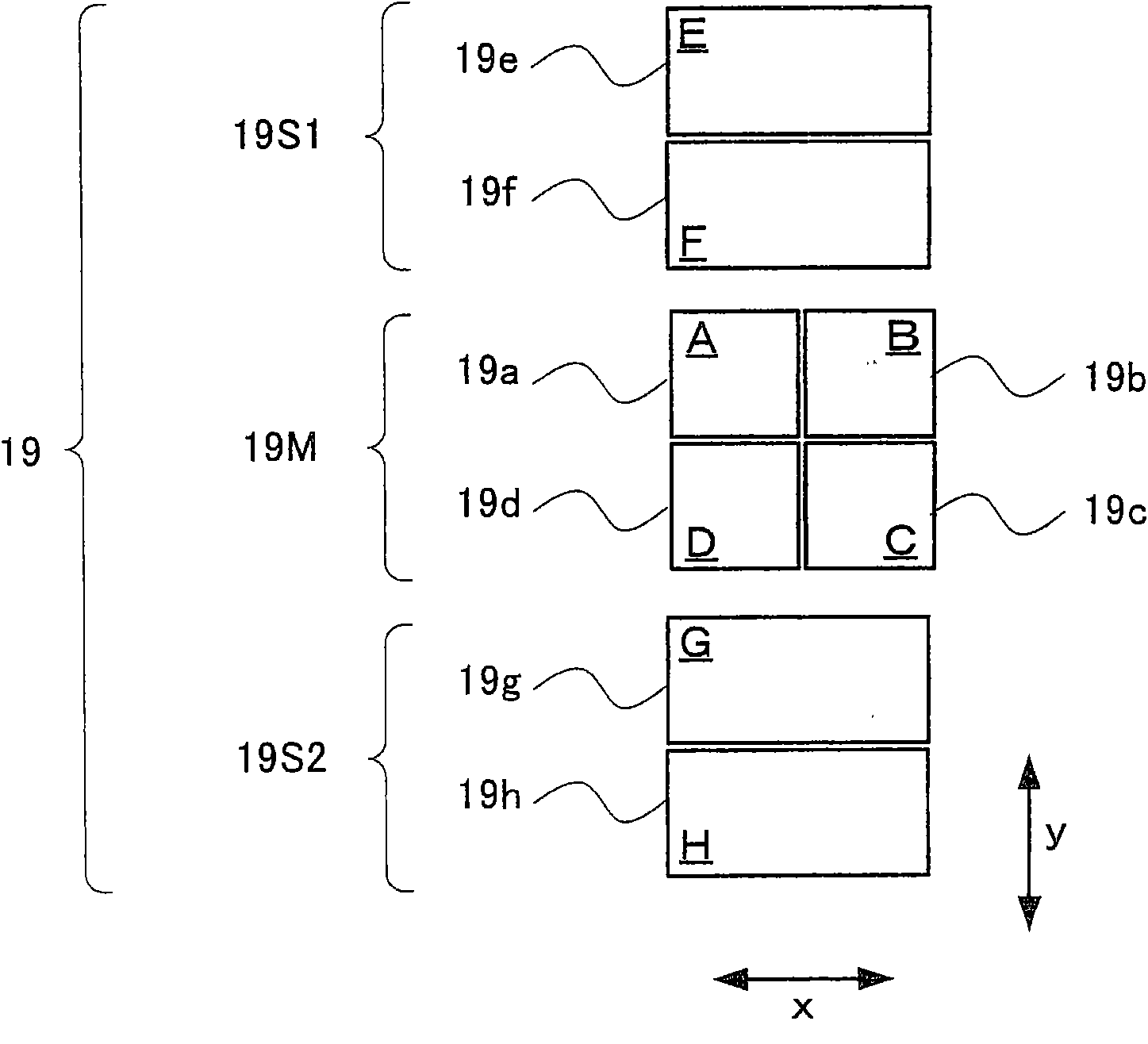
[0089] Figure 16 It is a plan view showing the lengths (widths) in the y direction of divided photosensitive elements and interference fringes caused by interlayer stray light in the photodetector of the optical head device according to Embodiment 2 of the present invention. The optical head device according to Embodiment 2 applies conditions different from those in Embodiment 1 as conditions related to the position and size of the divided photosensitive elements of the photodetector 19 . Therefore, in the description of Embodiment 2, also refer to Figure 5 as well as Figure 6 .

[0090] In Embodiment 2, the position of the dividing line between the divided photosensitive element 9e and the divided photosensitive element 9f in the sub-beam photosensitive portion 9S1 is set at a medium-strength position between the position where the intensity of the interference fringe is the strongest and the position where the intensity is the weakest. position, and the position of the...


PUM


Abstract

In an optical head device and an optical disc device, which make it possible to reduce an influence of a differential push-pull signal by stray light without making the structure complicated, reflective light of zero-order diffracted light by other information recording surfaces than an access subject information recording surface, reflective light of + first-order diffracted light by other information recording surfaces than an access subject information recording surface, and reflective light of - first order-order diffracted light by other information recording surfaces than an access subject information recording surface form an interference fringe on an optical detector (9). If a length in a y-direction of one period of the interference fringe is Ty, a positive integer is N1, and lengths in the y-direction of divided receiving elements (9e, 9f, 9g, 9h) are Uy, respectively, then they satisfy the following: Uy=Ty x N1. Further, if a positive integer is N2, a distance from the center of a main beam light receiving unit (9M) to the divided receiving elements (9e, 9f, 9g, 9h) and a distance from the center of the main beam light receiving unit (9M) to a dividing line of the divided receiving elements (9g, 9h) are Vy, then they satisfy the following: Vy = (Ty / 2) x {N2 - (1 / 2)}.

Description

technical field [0001] The present invention relates to an optical head device for irradiating laser light onto a multilayer optical disc having a plurality of information recording surfaces and detecting the reflected light, and an optical disc device having the optical head device. Background technique [0002] In optical discs 10 such as CD (Compact Disc), DVD (Digital Versatile Disc: Digital Versatile Disc), and BD (Blu-ray Disc: Blu-ray Disc), there are reproduction-only optical discs and record-once or rewritable discs. disc, such as figure 1 As shown, the reproduction-only optical disc is formed with an arrangement of spiral pits TB with a track pitch of TP on the information recording surface, that is, a recording track TR, as figure 2 As shown, a write-once or rewritable optical disc has a spiral recording track TR on which a recording mark TM is written with a track pitch of TP formed on the information recording surface. [0003] The optical disc device include...

Claims


Application Information

Patent Timeline
IPC IPC(8): G11B7/13G11B7/135G11B7/09
CPCG11B7/0903G11B7/0943G11B7/0906G11B2007/0013G11B7/131
Inventor 中原宏勋
Owner MITSUBISHI ELECTRIC CORP
Why Eureka
Try Eureka