Conveyor chain

A technology of chain and transmission system, which is applied in the field of tie chain or pin chain, and can solve the problems of central chain link wear and other problems

Inactive Publication Date: 2010-03-31
弗诺斯特链运有限公司
View PDF5 Cites 1 Cited by
  • Summary
  • Abstract
  • Description
  • Claims
  • Application Information

AI Technical Summary

Problems solved by technology

The balls can provide additional flexibility in the chain, but wear relative to the center link as the links move relative to the pins

Method used


Image

  • Conveyor chain
  • Conveyor chain
  • Conveyor chain

Examples


Embodiment Construction

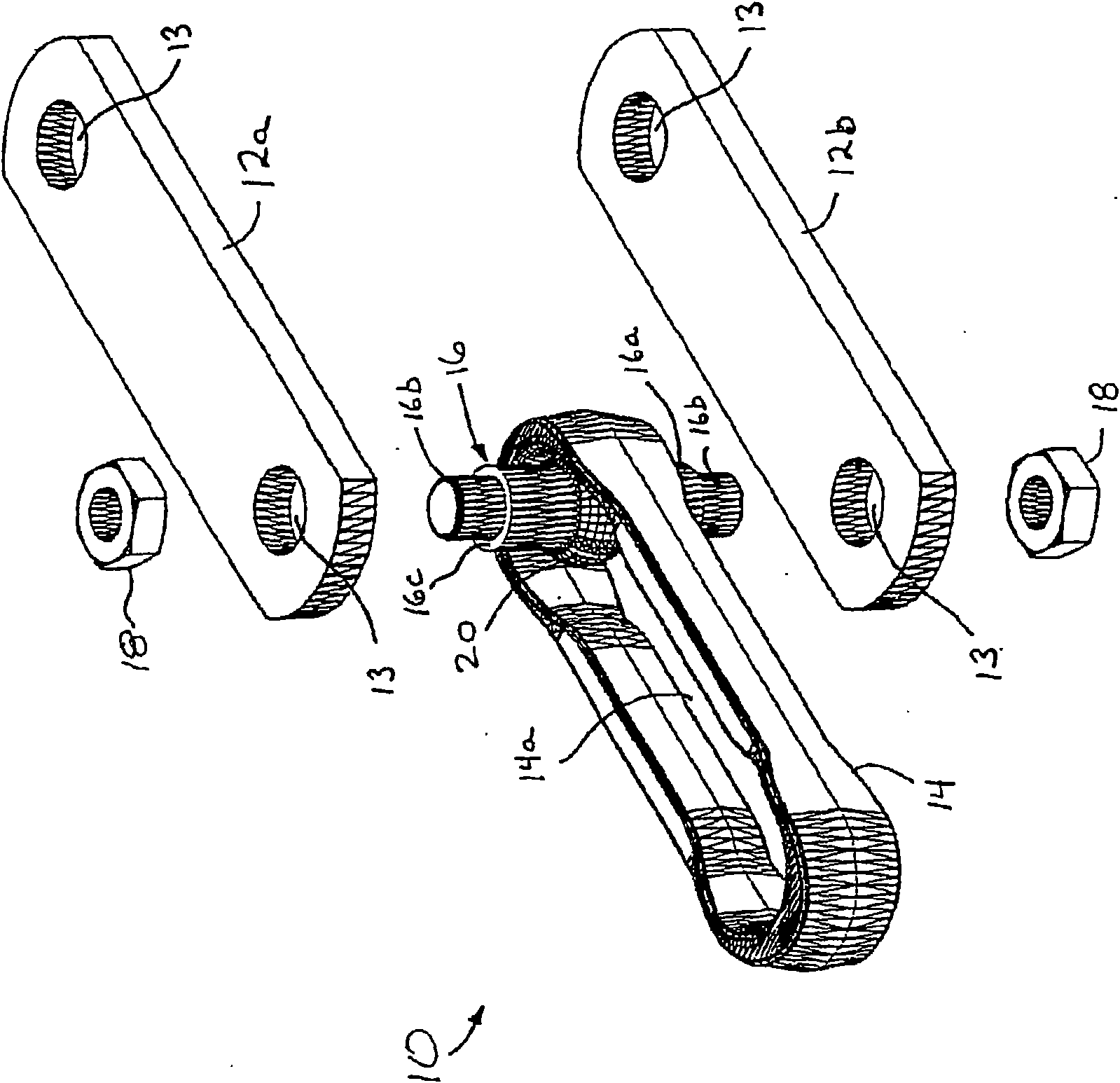
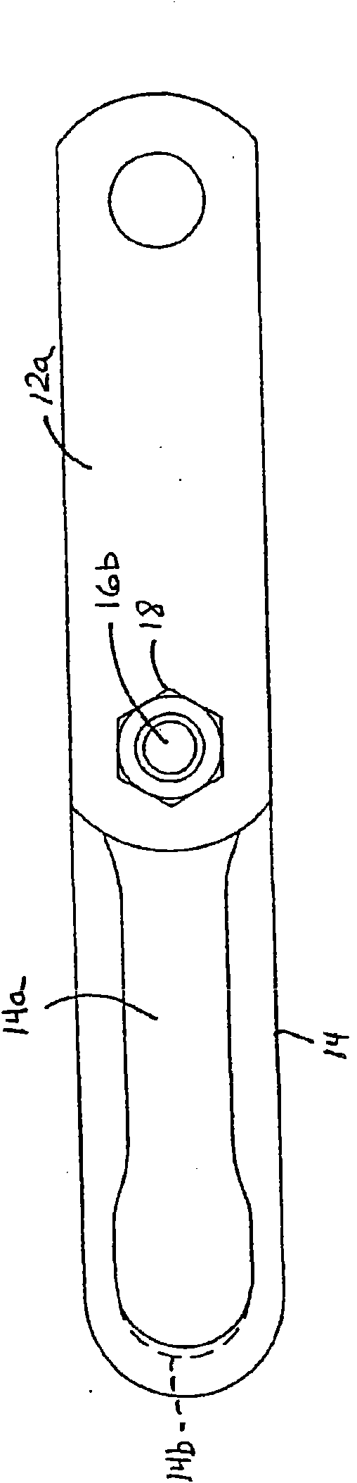
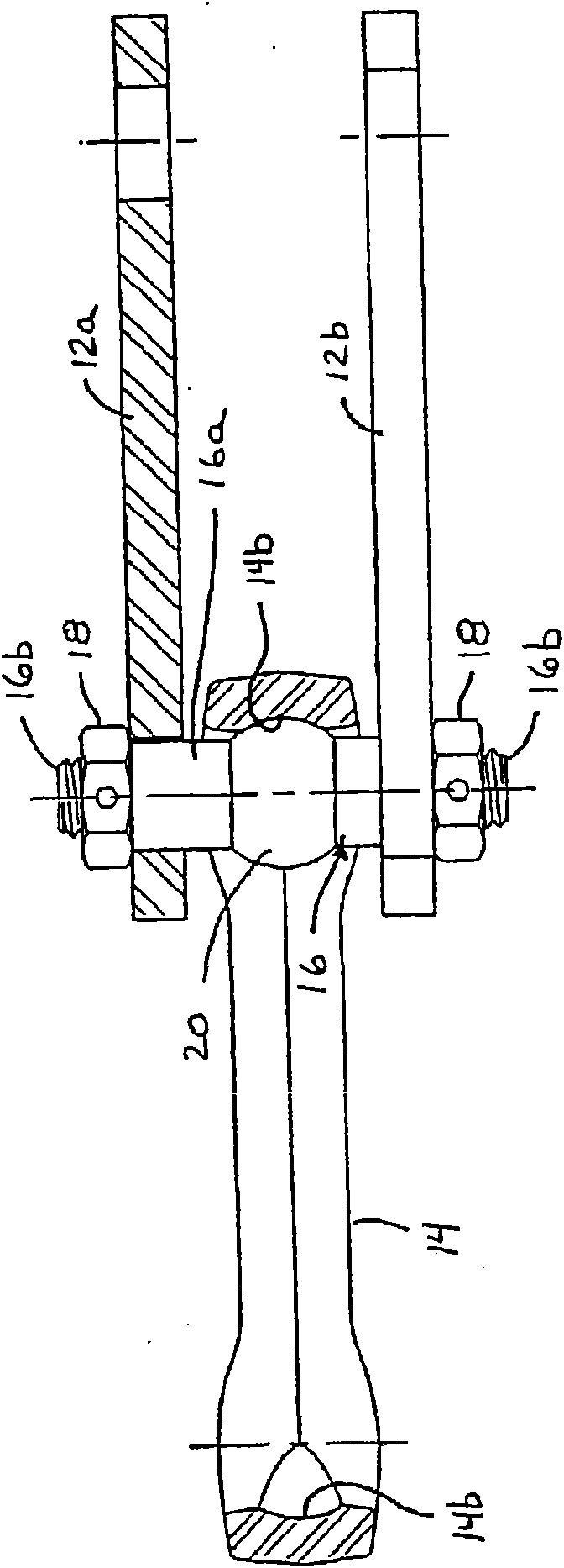
[0071] Referring now to the drawings and illustrating embodiments, a chain section 10 for transporting products along a transport system, such as a material handling or handling system, includes a pair of side links 12a, 12b and a center link 14 ( Figure 1-3 ). The central link 14 is held between the side links 12a, 12b by a stud or stud-type pin 16 which extends through the central region 14a of the central link 14 and into each side link 12a, 12b. The opening 13 of the opening 13 is held in it by a corresponding fixing piece or nut 18. The stud 16 includes a spherical or annular spherical member 20 generally seated at the midpoint and intermediate region of the shaft portion 16 a of the stud 16 . The chain 10 comprises a plurality of links connected together in a continuous loop around the conveyor system, as is known in the art. To simplify the description, only one group or part of the chain connections are shown, and the other chain connections are basically the same. ...


PUM


Abstract

A section of chain for conveying product along a material handling system includes a pin connecting a center link between two side links. The pin may have a sleeve portion around and at least partially along the shaft portion of the pin. The sleeve portion may engage a center link of the section of chain and may be movable relative to the shaft portion. The sleeve portion may comprise a polymeric material. The sleeve portion may be molded over an I-pin or the like, or may be slid or pressed onto a stud-ended pin or bolt or the like. The pin may include a generally spherical-shaped ball member or portion on the shaft portion to enhance flexibility of the section of chain. The pin may be dialable or selectably positioned at the side links to control and adjust the wear surface of the pin relative to the chain links.

Description

[0001] This application is a divisional application, and its parent case is a PCT application with an application date of March 7, 2003, an application number of 03810413.X, and an invention title of "transmission chain". [0002] The above parent application claims priority to earlier applications US60 / 362,751, US60 / 367,390, US60 / 381,518 and US60 / 425,577, the disclosures of which are incorporated herein by reference. technical field [0003] The present invention relates generally to chains of transmission systems and, in particular, to tethered or pinned chains allowing pivotal movement between a central chain and a pair of side chains about an axis defined by a bolt or pin extending therefrom. Background technique [0004] Chains used in power transmission or material handling systems, such as chains used to move multiple rollers or the like along a path in a processing plant, warehouse, etc., bend as the chain travels along a predetermined path. As the chain travels alon...

Claims


Application Information

Patent Timeline
Patent Type & Authority Applications(China)
IPC IPC(8): B65G17/38B65G17/40F16G13/06F16G13/10
CPCF16G13/06F16G13/10B65G17/38
Inventor 查尔斯·C·弗诺斯特
Owner 弗诺斯特链运有限公司
Why Eureka
Try Eureka