Optical element and imaging device

An optical component, optically transparent technology, applied in the direction of optical components, optics, electrical components, etc., can solve the problems of increasing the size of the device and reducing the image resolution.

An optical component, optically transparent technology, applied in the direction of optical components, optics, electrical components, etc., can solve the problems of increasing the size of the device and reducing the image resolution.

CN101685172AInactive Publication Date: 2010-03-31SONY CORP

Image

  • Optical element and imaging device
  • Optical element and imaging device
  • Optical element and imaging device

Examples


no. 1 approach

[0043] [Structure of Imaging Device]

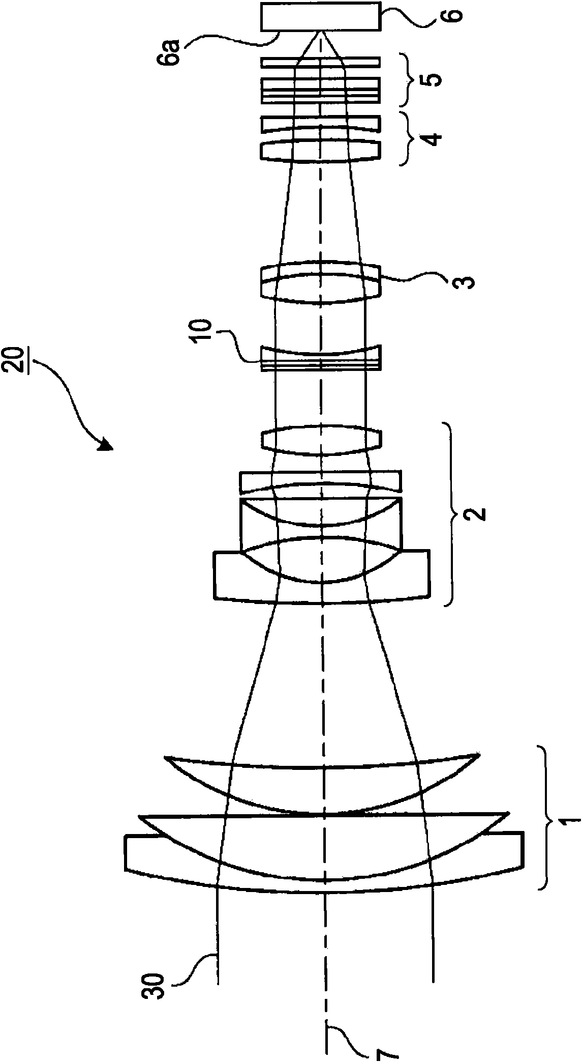
[0044] figure 1 An example of a schematic configuration of an imaging device to which the aperture mechanism of the present embodiment (hereafter referred to as “liquid iris”) is shown. figure 1 An example of an imaging device including a zoom mechanism (zoom mechanism) is shown. figure 1 The configuration of the optical system of the imaging device is mainly shown, and a portion configured to process an acquired image and a portion configured to perform control processing of the optical system are omitted. Embodiments of the present invention can also be applied to imaging devices that do not include a zoom mechanism.

[0045] The optical system of the imaging device 20 includes a first lens unit 1 , a second lens unit 2 , a liquid iris diaphragm 10 , a third lens unit 3 , a fourth lens unit 4 , a filter 5 and an imaging element 6 . The first lens unit 1, the second lens unit 2, the liquid iris diaphragm 10, the third lens unit 3, ...

no. 2 approach

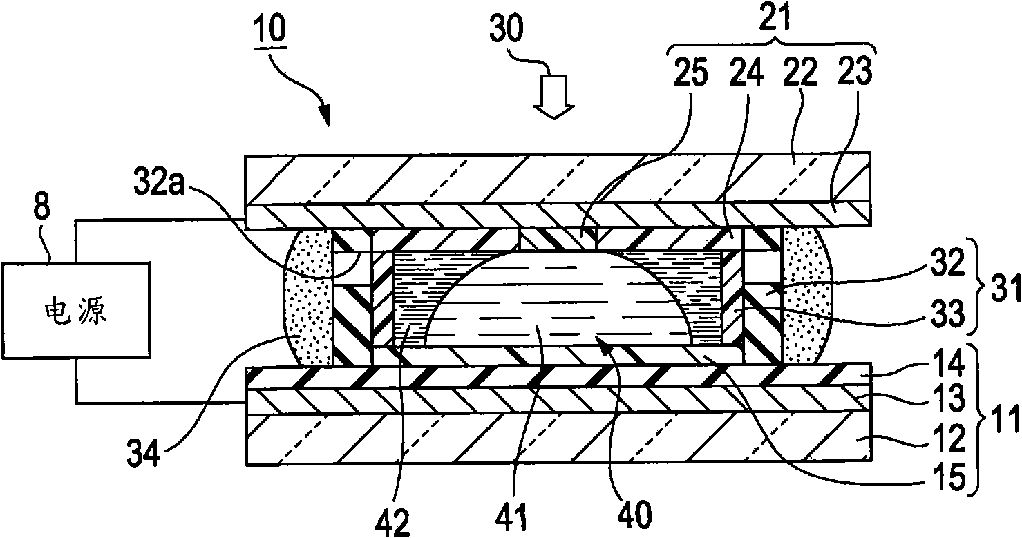
[0108] In the second embodiment, an example in which the structure of the first electrode is changed in the structure of the liquid iris diaphragm 10 of the first embodiment will be described.


PUM


Abstract

An optical element includes a first liquid; a second liquid that is immiscible with the first liquid and that has polarity or electrical conductivity; a first substrate portion, a second substrate portion, a sidewall portion; a second electrode disposed on one of the second substrate portion and the sidewall portion; and an accommodating portion constituted by the first substrate portion, the second substrate portion, and the sidewall portion and sealing the first liquid and the second liquid therein. The optical element further includes a first film disposed on the first substrate portion side of the accommodating portion and having high affinity with the first liquid, a second film disposed on the second substrate portion side of the accommodating portion and having high affinity with the second liquid, and a third film disposed at the center of the second film and having high affinity with the first liquid.

Description

[0001] References to related applications [0002] The present invention contains subject matter related to Japanese Priority Patent Application JP 2008-249240 filed in the Japan Patent Office on Sep. 26, 2008, the entire content of which is hereby incorporated by reference. technical field [0003] The present invention relates to optical elements and imaging devices. More particularly, the present invention relates to an optical element utilizing the electrowetting phenomenon and an imaging device including the same. Background technique [0004] In imaging optical systems used in imaging devices such as cameras and video cameras, these imaging optical systems are required to have functions of focusing and adjusting the amount of light to achieve natural defocusing, uniform distribution of the amount of light on the image surface, and the like. Among these requirements, generally, the requirement to adjust the amount of light is satisfied by a mechanical aperture mechanis...

Claims


Application Information

Patent Timeline
31 Mar 2010
Publication
CN101685172A
IPC
G02B5/00; G02B26/02; G03B9/02; G03B19/02; H04N5/225
CPC
G02B26/005; G02B3/14
Inventors
光田幸宽; 佐野幸广