Accuracy correcting method of laser marking machine

A technology of laser marking machine and calibration method, which is applied in the direction of computer parts, digital marking record carriers, instruments, etc. It can solve the problems of high-precision special industries that cannot meet the requirements, the accuracy of software calibration methods, calibration errors, and low calibration accuracy, etc. problem, to achieve the effect of simple method, improved efficiency and high calibration accuracy

Active Publication Date: 2010-03-31
HANS LASER TECH IND GRP CO LTD
View PDF0 Cites 25 Cited by
  • Summary
  • Abstract
  • Description
  • Claims
  • Application Information

AI Technical Summary

Problems solved by technology

The current software correction method faces the problem of low correction accuracy, especially for special industries that require high precision.
At the same time, since general scanners and other image acquisition devices are also faced with the deviation of position information during the image acquisition process caused by mechanical movement, this also brings errors to the accuracy correction of the software correction method

Method used


Image

  • Accuracy correcting method of laser marking machine
  • Accuracy correcting method of laser marking machine
  • Accuracy correcting method of laser marking machine

Examples


specific Embodiment approach

[0028] The present invention adopts the method of combining software and hardware to correct the marking accuracy of the laser marking machine, and the specific implementation method is as follows:

Embodiment approach 1

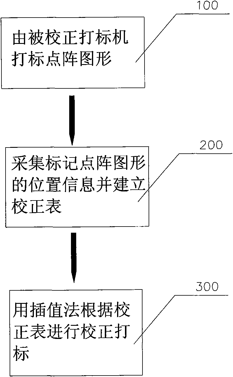
[0030] see figure 1 , is the flow chart of laser marking machine accuracy correction in the embodiment of the present invention, and the steps of the laser marking machine accuracy correction method in the present invention include:

[0031] Step 100: mark the dot matrix pattern by the corrected marking machine.

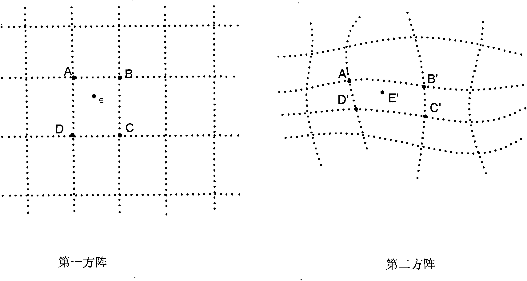
[0032] The marking system of the marking machine to be corrected issues a command to mark the dot matrix graphics, and the center point of the dot matrix graphics in the marking system command is taken to form a first square matrix, and the first square matrix is ​​more than two rows and two columns square array.

[0033] Step 200: Collect the position information of the marked dot matrix pattern and establish a correction table.

[0034] The position information of the center point of the dot matrix graphic on the marker is collected to form a second square matrix, and the points of the second square matrix correspond to the points of the first square matrix respe...

Embodiment approach 2

[0054] In the first embodiment, the square matrix formed by the center points of the dot matrix pattern on the marker is directly collected, that is, the second square matrix. Due to the irregularity of the second square matrix, when judging whether a point falls within the range of which points in the second square matrix, the amount of calculation is large, the calculation process is long, and it is difficult to confirm quickly. Therefore, in order to simplify the calculation , adopt the following implementation method:

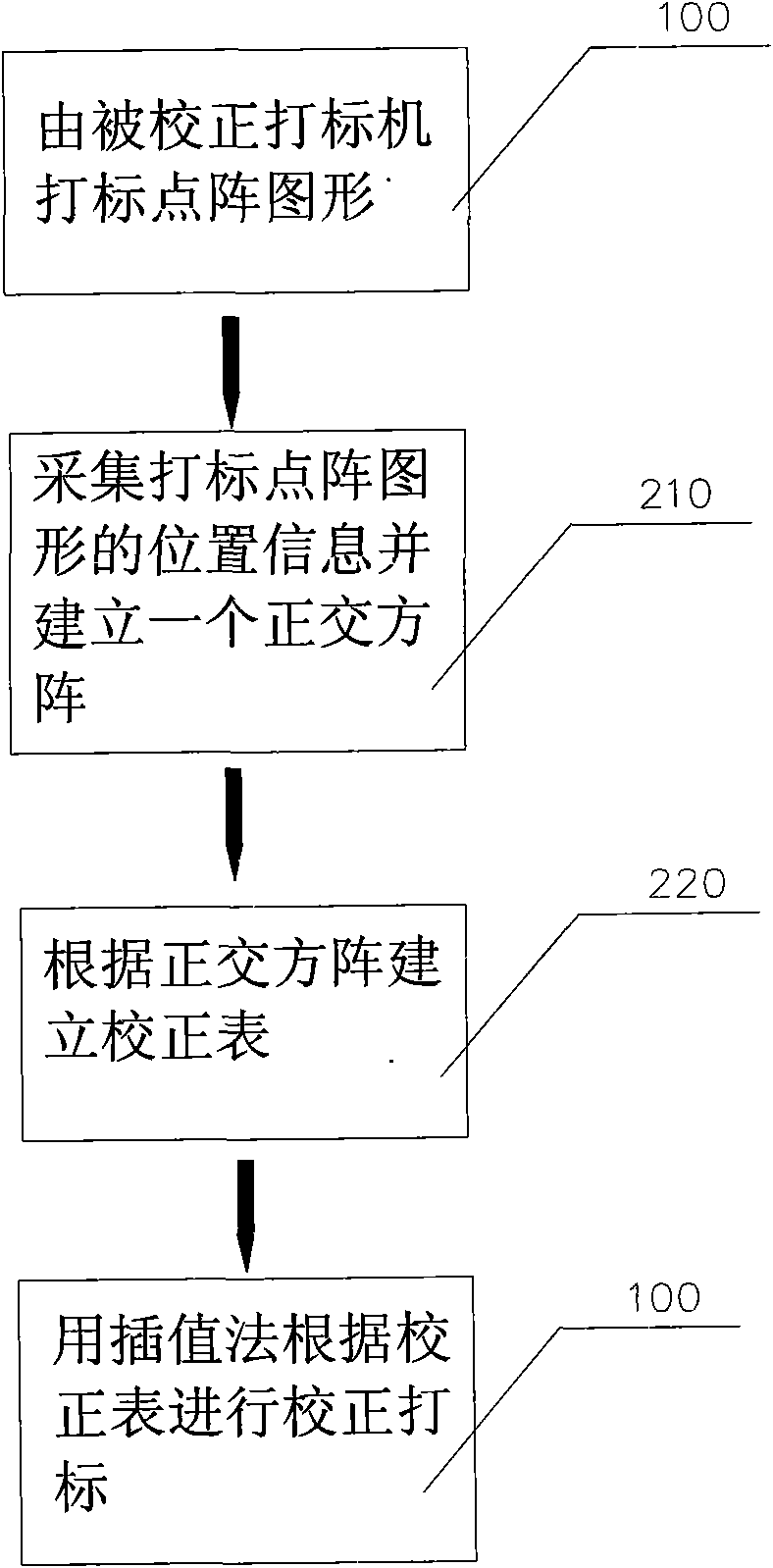
[0055] like image 3 As shown, it is a correction flowchart using an orthogonal square matrix. The implementation of this method includes the following steps:

[0056]Step 100: mark the dot matrix pattern by the corrected marking machine.

[0057] The marking system of the calibrated marking machine issues a command to mark the dot matrix graphics. The system commands the dot matrix graphics to be marked. The dot matrix graphics are a square matrix with m...


PUM


Abstract

The invention provides an accuracy correcting method of a laser marking machine, which comprises the following steps: collecting the position information of dots in a marking dot matrix of the laser marking machine, establishing a correction table by the collected position information of the dot matrix and the dot matrix in the system, and correcting marks by adopting an interpolation method. Simultaneously, in order to simplify the algorithm and reduce the implementation cost, methods of taking an orthogonal square matrix and correcting and marking an image collecting device are also adopted.The accuracy correcting method has high correcting accuracy, simple and convenient calculation and low implementation cost.

Description

technical field [0001] The invention relates to an accuracy correction method, in particular to an accuracy correction method for a laser marking machine. Background technique [0002] The laser marking system often involves equipment such as galvanometer scanning. Since there is a nonlinear correspondence between the deflection angle of the galvanometer and the plane coordinates, if a simple linear relationship is used to control the deflection of the galvanometer, the shape of the scan Distortion will occur, therefore, the accuracy of the laser marking system needs to be corrected. [0003] In the prior art, the accuracy of laser marking is mainly corrected in the following two ways: one is to correct by improving the scanning accuracy of the galvanometer and reducing the axial deviation, which is mainly corrected by hardware; the other is to The galvanometer is controlled by software dynamic compensation to correct distortion, which is mainly corrected by software. The ...

Claims


Application Information

Patent Timeline
Patent Type & Authority Applications(China)
IPC IPC(8): G06K1/12B41J2/435
Inventor 高云峰叶恒青谢琛
Owner HANS LASER TECH IND GRP CO LTD
Why Eureka
Try Eureka