RFID communication model air interface parameter testing method

A technology of communication model and test method, which is applied in the field of automatic identification, can solve the problem that the writing operation function of passive electronic tags cannot be included, and achieve the effect of easy prediction

Active Publication Date: 2010-03-31
CHINA ELECTRONICS TECH GRP NO 7 RES INST
View PDF4 Cites 5 Cited by
  • Summary
  • Abstract
  • Description
  • Claims
  • Application Information

AI Technical Summary

Problems solved by technology

In fact, the writing operation function of passive electronic tags also fails to include

Method used


Image

  • RFID communication model air interface parameter testing method
  • RFID communication model air interface parameter testing method
  • RFID communication model air interface parameter testing method

Examples


Embodiment Construction

[0025] 1. Basic concept of communication model

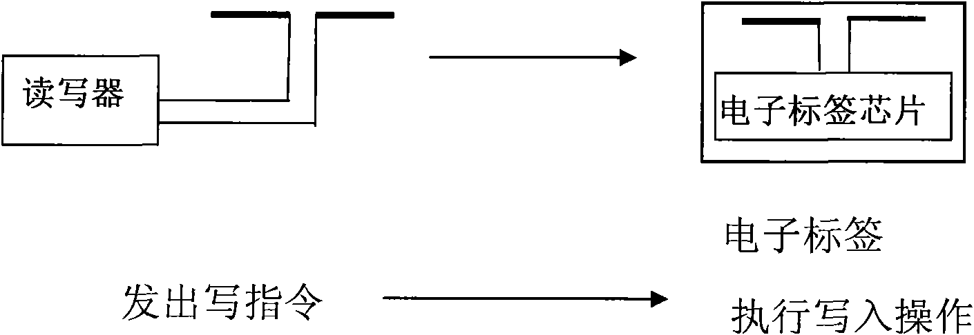
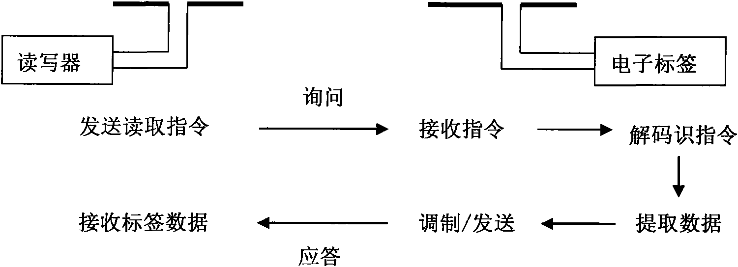
[0026] The RFID air interface suitable for the far-field electromagnetic field environment has two working modes, wireless writing mode and reading mode. Therefore, there are two communication models. RFID wireless write model (such as figure 1 ), RFID reading model (such as figure 2 ).

[0027] In the communication model, whether it is a write operation or a read operation, the electronic tag is not regarded as a pure backscatterer, so the concept of radar cross section is no longer used. For write operations, consider the electronic tag to be a terminal node on the communication link. It is a complete transceiver device. Therefore, it should have receiving sensitivity, transmitting power. For the reading operation, we regard the entire process of inquiry and response as a relay link, then the electronic tag can be regarded as a forwarding node, and the ratio of the tag's transmitting power to receiving sensitivity shoul...


PUM


Abstract

A radio frequency identification (RFID) communication model air interface parameter testing method of the invention relates to the RFID, a current radar model air interface parameter definition and atesting method, and the invention mainly pays attention to parameters like wave forms, time, radar sections and the like. The invention provides two communication models of RFID writing and reading (the reading model is shown in the figure) and pays attention to related system device capacity. The method comprises parameter definitions and testing methods like sensitivity of label writing and reading, transmitted power, transceiving gain, receiving sensitivity of a reader and degree of symmetry of uplink and downlink channels. The invention provides a quoted auxiliary radio frequency identification, which is a method for determining the detected radio frequency identification and the reader parameter through reckoning by parameter testing. The invention is applicable to the RFID air interface working in far-field electromagnetic field, comprising quality assessment of products in each frequency range of UHF and MW, design improvement and application engineering design.

Description

technical field [0001] The invention belongs to the field of automatic identification, especially for the research, design and production of UHF and higher frequency radio frequency identification (RFID) air interfaces, and is used for detecting and checking the quality assessment of product air interface parameters. Background technique [0002] Radio Frequency Identification (RFID) technology has been brewing for decades, and its working frequency ranges from low frequency to high frequency, and then to UHF and microwave. In recent years, low frequency to high frequency has matured. It began to usher in large-scale and wide-ranging applications. UHF and higher frequency bands are in the stage of technological growth, and both equipment design technology, system application technology, and even standard formulation are still under development. [0003] Radio frequency identification (RFID) is about to form a big industry. UHF and higher frequency band RFID will greatly e...

Claims


Application Information

Patent Timeline
Patent Type & Authority Applications(China)
IPC IPC(8): G06K7/00
Inventor 刘礼白
Owner CHINA ELECTRONICS TECH GRP NO 7 RES INST
Why Eureka
Try Eureka