Method for detecting frequency errors of sampling clock, device and system thereof
A sampling clock and frequency error technology, applied in the field of signal processing, can solve the problems of sampling clock frequency error, RAKE receiver implementation complexity, etc., and achieve the effect of moderate complexity
- Summary
- Abstract
- Description
- Claims
- Application Information
AI Technical Summary
Problems solved by technology
Method used
Image
Examples
Embodiment 1
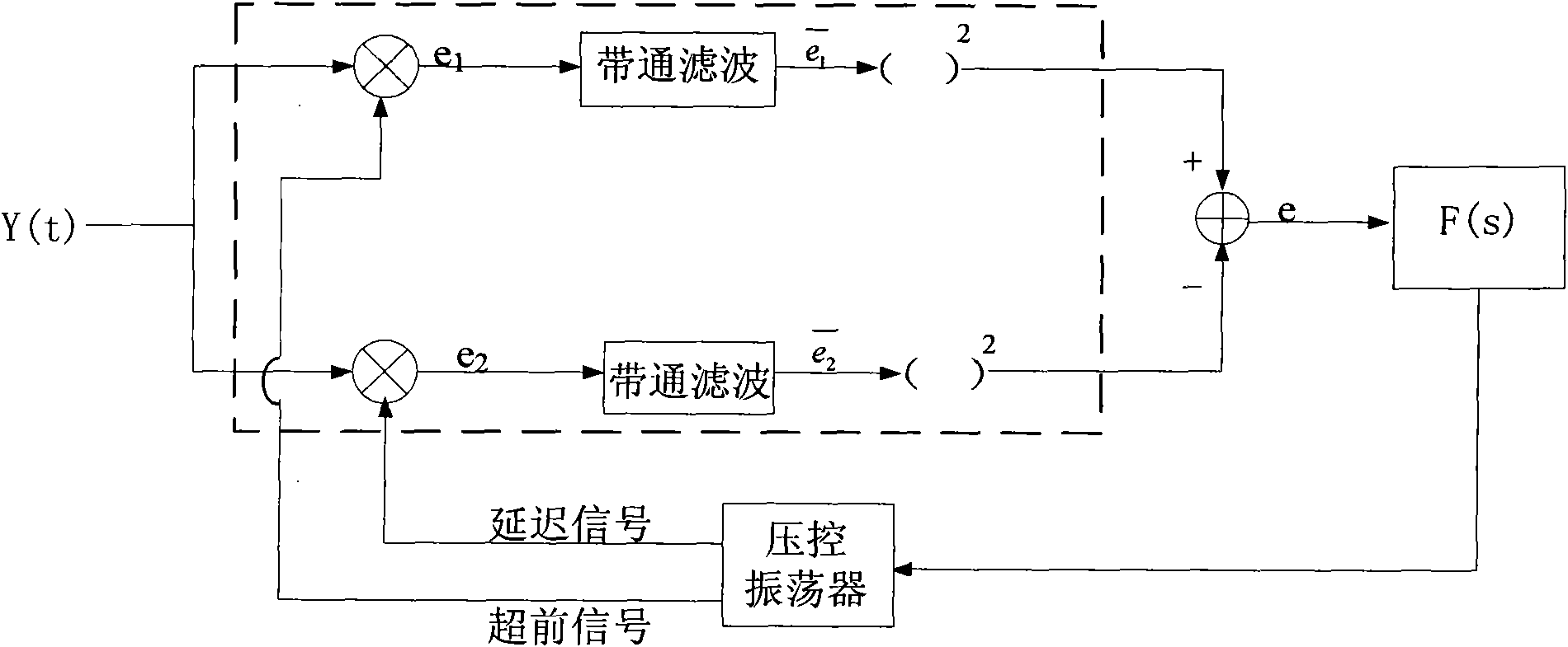
[0045] See Image 6 It is a flowchart of a method for detecting a sampling clock frequency error in Embodiment 1 of the present invention, as Image 6 As shown, the embodiment of the present invention provides a method for detecting a sampling clock frequency error, including:
[0046] Step 601: According to the received two-period pseudo-random sequences, respectively calculate and obtain the partial channel impulse responses on the two-period pseudo-random sequences;
[0047] In one implementation, step 601 may include: correlating the received two-period pseudo-random sequences with known pseudo-random sequences, and calculating the channel impulse response on the two-period pseudo-random sequences;
[0048] From the channel impulse response of the pseudo-random sequence of these two periods, select the same main path, take M points on the left and right sides of the main path, M is a positive integer, and form two points with 2M+1 points respectively The partial channel ...
Embodiment 2
[0062] See Figure 7 It is a flowchart of a method for detecting a sampling clock frequency error in Embodiment 2 of the present invention, as Figure 7 As shown, the embodiment of the present invention provides a method for detecting a sampling clock frequency error, including:
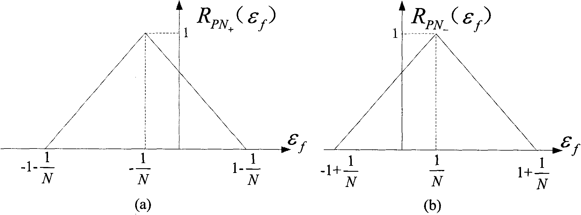
[0063] Step 701: see Figure 8 The two periodic PN sequences shown (can also be other pseudo-random sequences, according to system design), they may be adjacent or non-adjacent, and may be separated by other PN sequences or data in the middle, through the received The two periodic PN sequences are time-domain correlated with the local known PN sequence as the pilot signal, and the channel impulse response can be calculated on the two periodic PN sequences; for the convenience of understanding, it needs to be explained that: The channel impulse response here may be a complete channel impulse response, as shown in the figure formed by cascading multiple Figures 9(a) or 9(b);
[0064] Step 702: Accor...
Embodiment 3
[0076] See Figure 11 It is a schematic structural diagram of a frequency discriminator in Embodiment 3 of the present invention, such as Figure 11 As shown, the embodiment of the present invention provides a frequency discriminator, including:
[0077] The calculation module 11A is configured to calculate the partial channel impulse responses on the pseudo-random sequences of the two periods respectively according to the received pseudo-random sequences of the two periods;
[0078] A correlation module 11B, configured to correlate the two partial channel impulse responses, and obtain a related waveform;
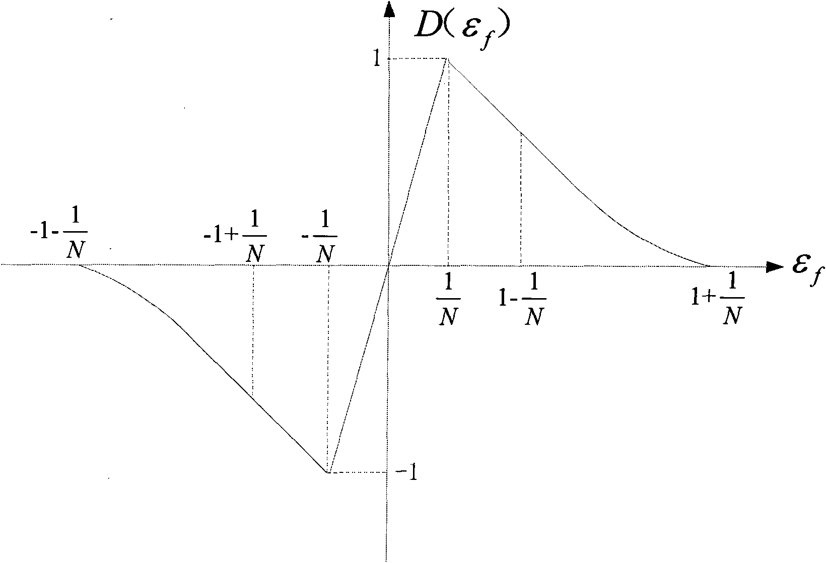
[0079] The detection module 11C is configured to perform lead-lag sampling time estimation on the related waveform, and detect the error of the sampling clock frequency according to the output result of the lead-lag sampling time estimation.
[0080]In one implementation, the calculation module 11A is the first calculation module, which is used to correlate the received t...
PUM
 Abstract
Description
Claims
Application Information
 - R&D
- Intellectual Property
- Life Sciences
- Materials
- Tech Scout
- Unparalleled Data Quality
- Higher Quality Content
- 60% Fewer Hallucinations
Browse by: Latest US Patents, China's latest patents, Technical Efficacy Thesaurus, Application Domain, Technology Topic, Popular Technical Reports.
© 2025 PatSnap. All rights reserved.Legal|Privacy policy|Modern Slavery Act Transparency Statement|Sitemap|About US| Contact US: help@patsnap.com


