Antistatic tool

An anti-static and appliance technology, applied in the direction of static electricity, application, circuit, etc., can solve problems such as the inability to fully solve the pressure marks, achieve reliable anti-static performance, improve yield and workability, and prevent explosions.

Inactive Publication Date: 2010-03-31
SEKISUI PLASTICS CO LTD
View PDF2 Cites 2 Cited by
  • Summary
  • Abstract
  • Description
  • Claims
  • Application Information

AI Technical Summary

Problems solved by technology

[0020] Furthermore, although wristbands or glove-type antistatic tools using stretchable conductive fibers rarely cau

Method used


Image

  • Antistatic tool
  • Antistatic tool
  • Antistatic tool

Examples


Embodiment 1

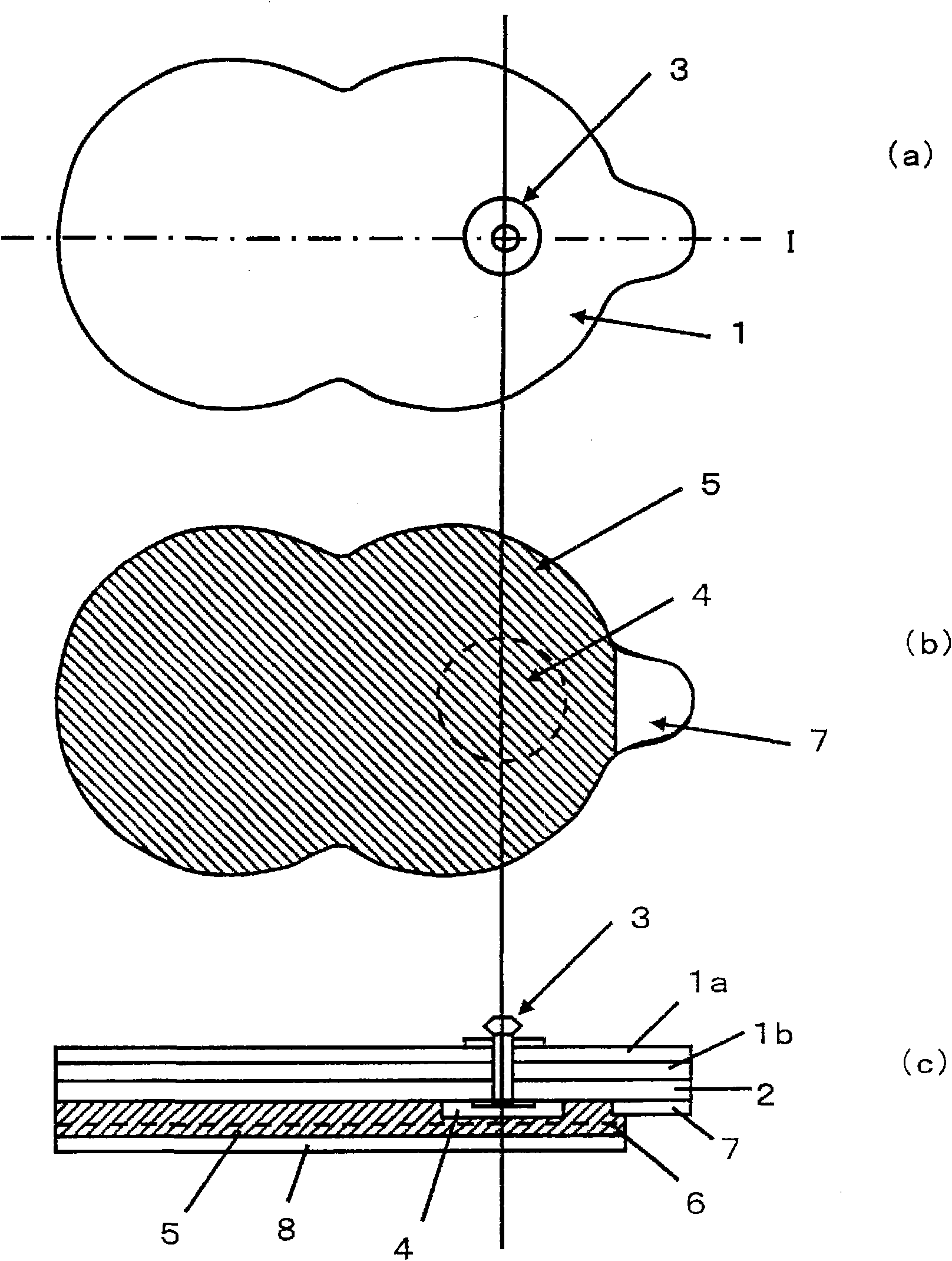
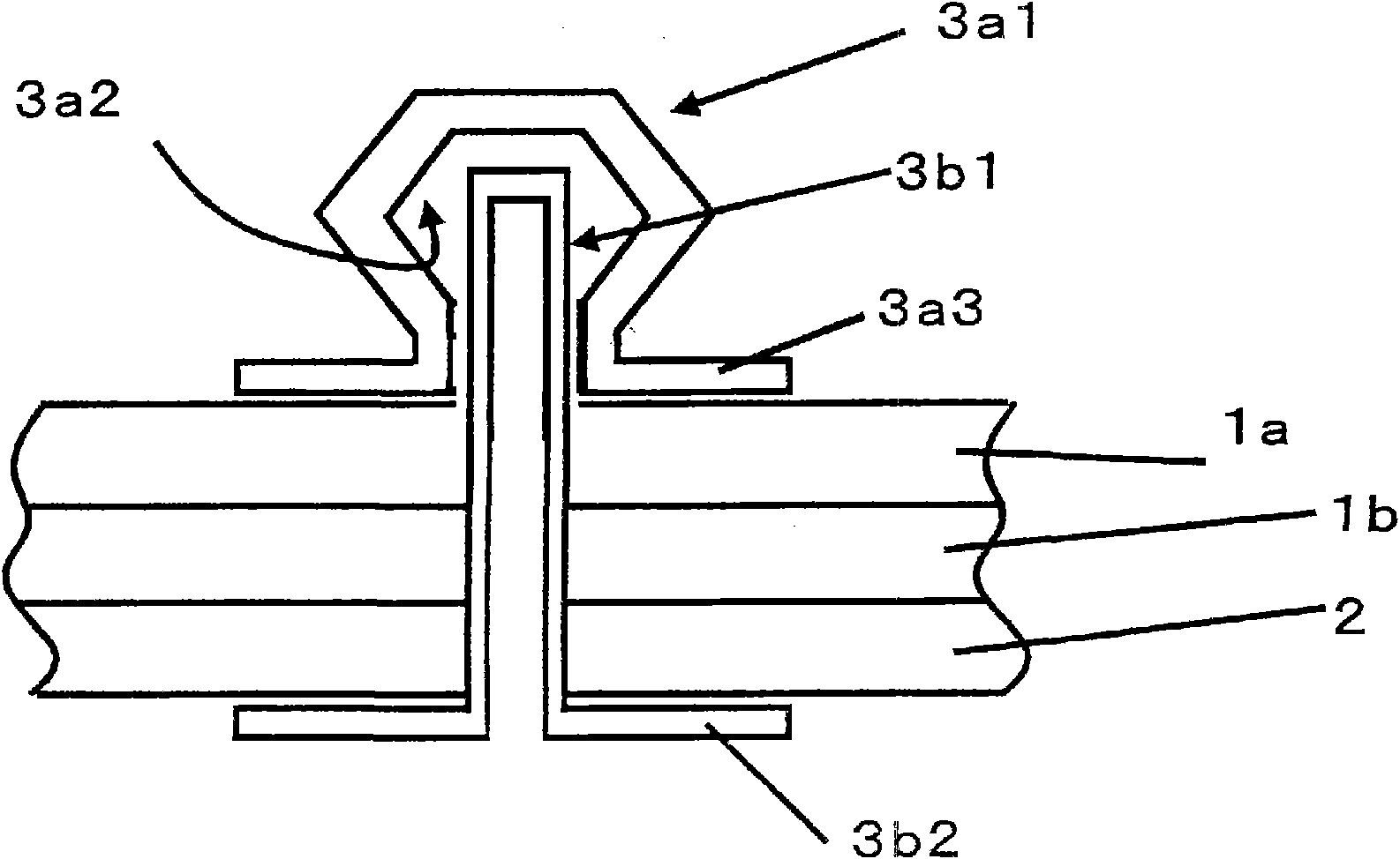
[0105] figure 1 (a)~(c) and figure 2 A schematic diagram of the antistatic appliance of Example 1 is shown in . figure 1 (a) is the top view schematic diagram of the antistatic appliance of embodiment 1, figure 1 (b) is the rear view schematic diagram of the antistatic appliance of embodiment 1, figure 1 (c) is the schematic sectional view of the I-I line of the antistatic appliance of embodiment 1, figure 2 yes figure 1 (c) An enlarged schematic view of the terminal portion. In addition, in figure 1 (a)~(c) and figure 2 Among them, reference numeral 1 is a supporting member, 1a is a soft polyethylene layer, 1b is a polyester film, 2 is a conductive layer, 3 is a terminal part, 3a is a conductive snap button, 3b is a conductive part, 4 is a cover layer, 5 is the conductive adhesive layer, 6 is the intermediate substrate, 7 is the non-adhesive layer, 8 is the protective film, 3a1 is the convex part of the conductive snap, 3a2 is the concave part of the conductive snap...

Embodiment 2

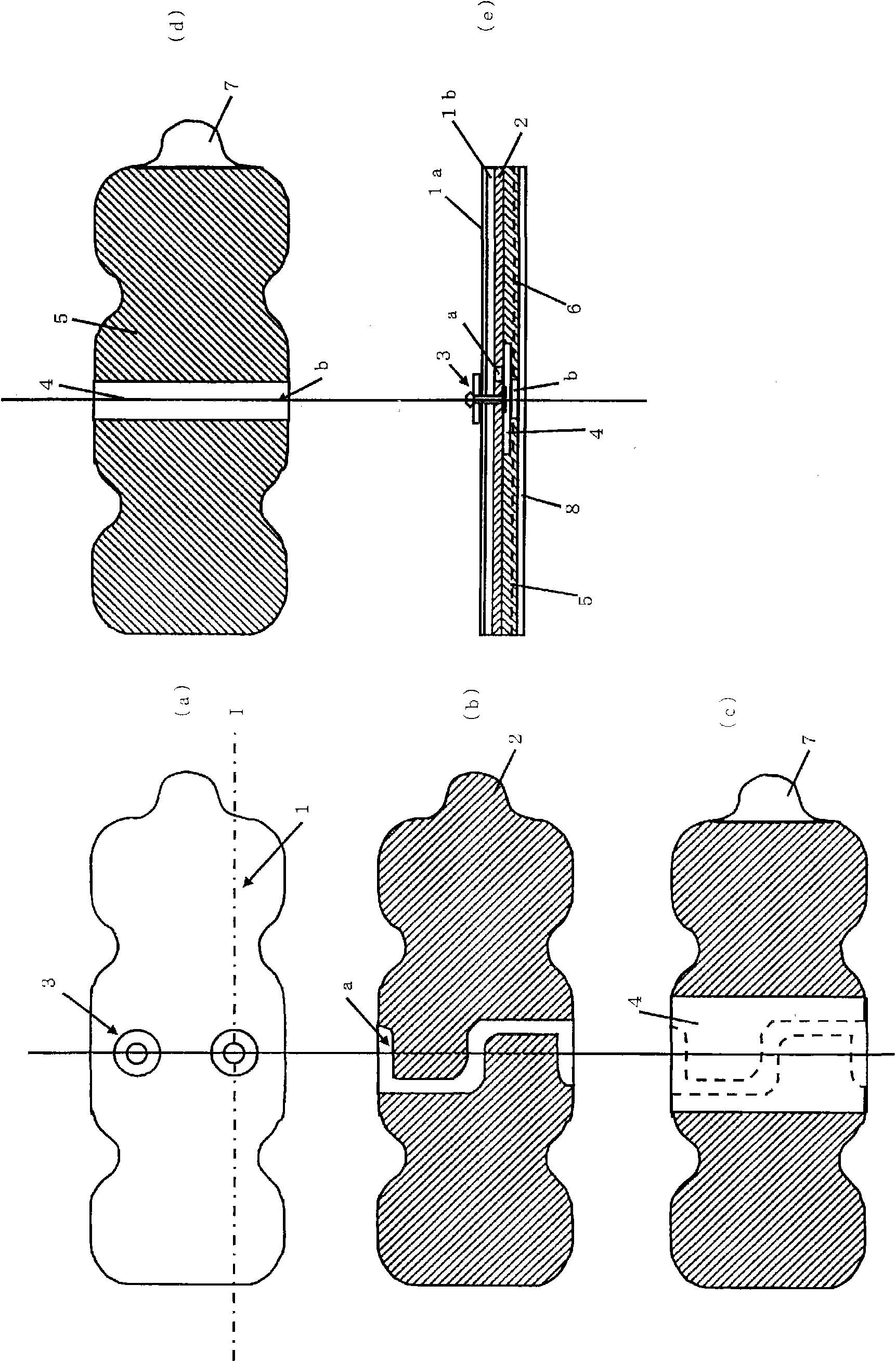
[0130] image 3 (a)-(e) shows the schematic diagram of the 2-terminal type antistatic tool of Example 2. image 3 (a) is the top view schematic diagram of the antistatic appliance of embodiment 2, image 3 (b) is a figure which shows the arrangement|positioning of the electroconductive layer of the antistatic tool of Example 1. image 3 The hatched portion in (b) is a conductive layer, and there is an S-shaped portion a where no conductive layer is formed near the center. image 3 (c) The figure which shows the state which laminated|stacked the covering layer and the non-adhesive layer. image 3 (d) The figure which shows the state which laminated|stacked the electroconductive adhesive layer. image 3 In (d), there exists a part b in which the electroconductive adhesive layer is not formed. image 3(e) is a schematic cross-sectional view of the I-I line of the antistatic appliance in embodiment 2. The terminal part of the antistatic appliance of embodiment 2 has figure ...


PUM

PropertyMeasurementUnit
Surface areaaaaaaaaaaa
Resistivityaaaaaaaaaa

Abstract

This invention provides an antistatic tool which, even when the surface form is complicated as in the human body, can realize good adhesion and can effectively remove charges electrified on its surface. A wristband-type antistatic tool suffers from a problem that, when it is fixed for a long period of time, for example, rashing derived from sweating, rashing derived from metal allergy, discomfortcaused by compression, and tightening mark occur in a wrist of a worker. The antistatic tool comprises a support member, an electroconductive layer provided on at least one face side of the support member, a terminal part which has a guard part at its lower end and extends through the support member so that the guard part comes into contact with one side of the electroconductive layer, a coveringlayer for covering the whole lower face of the guard part, and an electroconductive pressure sensitive adhesive layer stacked on the covering layer and the electroconductive layer. The antistatic tool is applied directly to the skin and is brought into intimate contact with the skin by the adhesive power possessed by the electroconductive pressure sensitive adhesive. Accordingly, the adhesion is not influenced, for example, by the difference in skin conditions between individual humans and the difference in physical condition-derived skin conditions, and continuous adhesion to the skin can beensured.

Description

technical field [0001] The invention relates to an antistatic appliance. More specifically, the present invention relates to an antistatic device that can adhere well even to complex surface shapes such as the human body and can effectively remove charges on the surface. The antistatic tool of the present invention is used as a tool for preventing workers from being charged with static electricity in the operation of semiconductor devices, circuits mounted on semiconductor devices, information recording equipment, etc., dust treatment, and chemical substances such as organic solvents. is useful. Furthermore, the antistatic tool of the present invention is useful for operations such as handling of hard disk drives or finer semiconductor devices in a working environment such as a clean room where fugitive dust is particularly prohibited. Background technique [0002] As we all know, static electricity charged by the human body can cause various problems. [0003] For exampl...

Claims


Application Information

Patent Timeline
IPC IPC(8): H05F3/02H01R4/64
CPCA61B5/411A61B5/04087H01R13/6485A61N1/14H01R4/64A61B5/259
Inventor 西哲也吉川和宏
Owner SEKISUI PLASTICS CO LTD
Why Eureka
Try Eureka