
Self-propelled lifter

A lift and self-propelled technology, which is applied in the field of construction machinery, can solve problems such as danger to workers and impact on work, and achieve the effect of improving performance, safety and reliability of work

Inactive Publication Date: 2010-04-07
SANY GRP
View PDF0 Cites 13 Cited by
  • Summary
  • Abstract
  • Description
  • Claims
  • Application Information

AI Technical Summary

Problems solved by technology

In this way, when the self-propelled elevator is in the process of lifting, when the internal combustion engine fails or lacks oil and the work stops, the self-propelled elevator may stop in the air, which not only affects its normal work, but also may affect the work of the self-propelled elevator. people pose danger

Method used


Image

  • Self-propelled lifter
  • Self-propelled lifter
  • Self-propelled lifter

Examples


Embodiment Construction

[0023] The core of the present invention is to provide a self-propelled lift, which has good performance, high working reliability and safe use.

[0024] In order to enable those skilled in the art to better understand the technical solutions of the present invention, the present invention will be further described in detail below in conjunction with the accompanying drawings and specific embodiments.

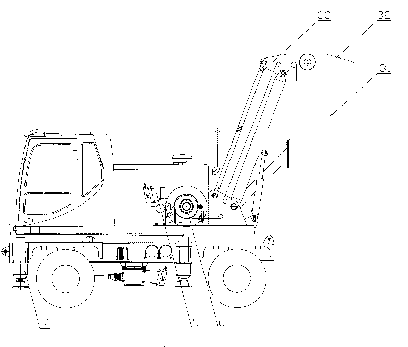
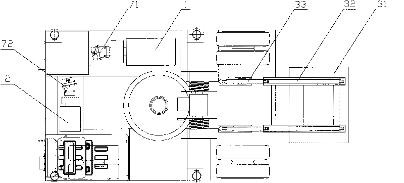
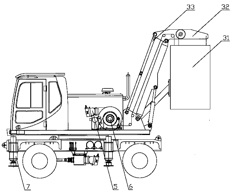
[0025] Please refer to figure 1 and figure 2 , figure 1 It is a schematic diagram of the mechanism of a specific embodiment of the self-propelled lift provided by the present invention; figure 2 A structural schematic diagram of a specific embodiment of the self-propelled lift provided by the invention in a top view direction.

[0026] In a specific embodiment, the self-propelled lift provided by the present invention includes a first power device, a second power device, and a control device for providing power for the boarding part or the getting off part. During the wor...


PUM


Abstract

The invention discloses a self-propelled lifter, which comprises an upper vehicle part and a lower vehicle part. The upper vehicle part further comprises a basket (31) which can be moveably arranged at the main body of the self-propelled lifter and also comprises a first power unit, a second power unit and a control unit for supplying power for the upper vehicle part or the lower vehicle part. During the working of the upper vehicle part, the control unit controls the second power unit to start when the first power unit stops working, and thus, dangers caused by sudden power loss of the upper vehicle part are prevented; meanwhile, the self-propelled lifter can be supplied with power not only by the first power unit but also through the second power unit, so various power output modes are provided; and being capable of going down to a depth of about 110 meters, the basket (31) of the self-propelled lifter of the invention can meet the use requirement under specific working conditions.

Description

technical field [0001] The invention relates to the field of engineering machinery, in particular to a self-propelled lift. Background technique [0002] With the rapid development of my country's economic construction, the market demand for construction machinery, especially self-propelled lifts is increasing. [0003] In some production and operation occasions, regular maintenance and overhaul of equipment is required. For example, when equipment such as permanent ship locks in water conservancy projects are overhauled, maintained and observed, staff need to enter the corridor of the ship lock to overhaul some equipment. If it is adopted to build working platforms such as scaffolding, the staff need to climb the scaffolding to enter the workplace, the labor intensity is relatively high, and the tools or materials used during maintenance also need to be completed by manpower or other lifting tools. Complex, waste a lot of manpower and material resources, and work efficienc...

Claims


Application Information

Patent Timeline
IPC IPC(8): B66F11/04B66F17/00B60P3/14B60K6/20
CPCB66F11/04
Inventor 喻志兵
Owner SANY GRP
Learn More