Spine clamp-spring connected clutch release bearing

A technology for separating bearings and clutches, applied in clutches, mechanical drive clutches, ball bearings, etc., can solve problems such as low production efficiency, unreliable connection, and increased labor intensity, and achieve improved production efficiency, reliable connection, and reduced labor intensity. Effect

Inactive Publication Date: 2010-04-07
MUDANJIANG BRYCO METAL PRODS
View PDF0 Cites 2 Cited by
  • Summary
  • Abstract
  • Description
  • Claims
  • Application Information

AI Technical Summary

Problems solved by technology

[0003] The existing clutch release bearings have the disadvantages that the connection between the bearing and the bearing seat is not reliable enough, or the processing technology and assembly process are not ideal, the production efficiency is low, and the labor intensity is increased.

Method used


Image

  • Spine clamp-spring connected clutch release bearing
  • Spine clamp-spring connected clutch release bearing
  • Spine clamp-spring connected clutch release bearing

Examples


Embodiment Construction

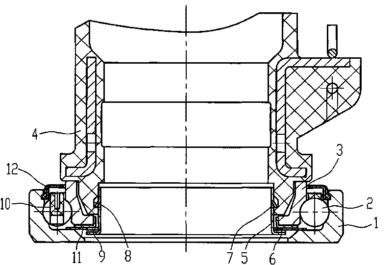
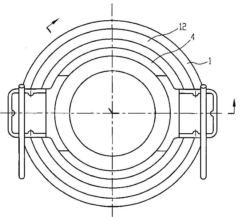
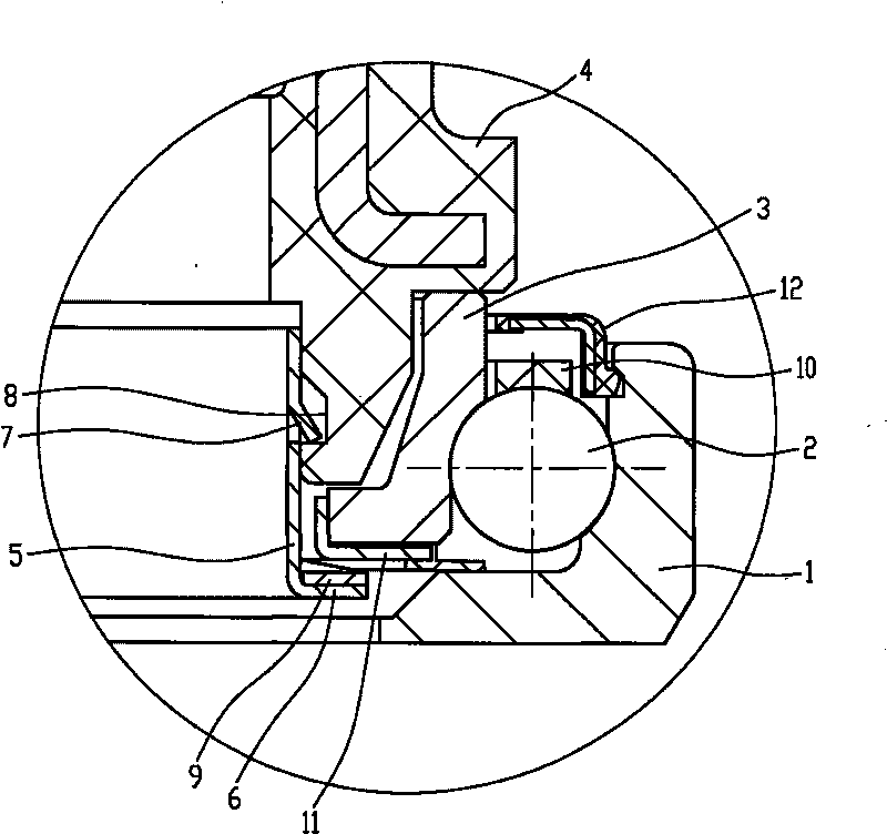
[0010] Such as figure 1 , 2 As shown in and 3, the ratchet-shaped circlip connection type clutch release bearing of this embodiment includes an outer ring 1, a roller 2, an inner ring 3, a bearing seat 4 and a ratchet-shaped circlip 5, and the ratchet-shaped circlip 5 is provided at the lower end. There is a circular body with an outer flanging 6, and the outer wall of the thorn-shaped circlip 5 is evenly distributed with thorns 7 facing downward. The ring 3 is set on the outside of the lower port of the bearing seat 4, and the ratchet-shaped circlip 5 is fixed on the inner side of the lower port of the bearing seat 4 through the thorn body 7. There is an annular pressing ring between the lower end surface of the inner ring 3 and the outer flange 6 of the ratchet-shaped circlip 5. Spring 9, the lower end surface of inner ring 3 is limited by the outward flange 6 of stage clip 9 and ratchet jumper 5.

[0011] A cage 10 is provided between the outer ring 1 and the inner ring 3...


PUM


Abstract

The invention relates to a spine clamp-spring connected clutch release bearing, belong to the automobile parts. The spine clamp-spring connected clutch release bearing comprises an outer ring (1), a roller (2), an inner ring (3), a bearing block (4) and a spine clamp-spring (5); the lower end of the spine clamp-spring (5) is provided with an externally turned-over edge (6), and spines (7) facing downwards are evenly distributed on the outer wall of the spine clamp-spring (5); the inner edge of the lower end opening of the bearing block (4) is provided with an annular clamp slot (8); the inner ring (3) is sleeved outside the lower end opening of the bearing block (4); the spine clamp-spring (5) is fixed inside the lower end opening of the bearing block (4) through the spines (7); and an annular compression spring is arranged between the lower end surface of the inner ring (3) and the externally turned-over edge (6) of the spine clamp-spring (5). The spine clamp-spring connected clutch release bearing has the advantages of reliable connection, hard disassembly, good processing and assembling technique, improves the production efficiency by about 40 percent compared with the other clutch release bearing connected in other common connection modes and greatly reduces the labor intensity.

Description

technical field [0001] The invention relates to auto parts, in particular to a clutch release bearing connected by a ratchet-shaped circlip. Background technique [0002] In general, clutch release bearings are composed of bearing housings, angular contact ball bearings, seals, elastic couplings, etc., and are an important part of the clutch release system. The clutch disengagement system is a mechanical device that cuts off the power transmission between the car engine and the drive line. It is customary to use a mechanical connection or a hydraulic device to apply pressure to the clutch release bearing through the clutch release control lever (shift fork), and the clutch release bearing then pushes or pulls up the clutch diaphragm spring to separate the engine from the power transmission line, thereby achieving The purpose of starting, stopping and shifting the car. [0003] In the existing clutch release bearing, the connection between the bearing and the bearing seat i...

Claims


Application Information

Patent Timeline
Patent Type & Authority Applications(China)
IPC IPC(8): F16D23/14F16C19/02F16B1/02
Inventor 马明君孙爱武
Owner MUDANJIANG BRYCO METAL PRODS
Why Eureka
Try Eureka