
Switch cabinet drawer interlocking mechanism

A technology of interlocking mechanism and switchgear, applied in the direction of pull-out switchgear, switchgear, electrical components, etc., can solve the problems of increasing the volume of the transmission part, occupying the installation position of the instrument panel, and increasing the production cost, and achieves a simple structure. , convenient processing and installation, and the effect of reducing production costs

Active Publication Date: 2011-05-11
WENZHOU ZHONG YI LOCK ELECTRIC CO LTD
View PDF0 Cites 1 Cited by
  • Summary
  • Abstract
  • Description
  • Claims
  • Application Information

AI Technical Summary

Problems solved by technology

[0002] At present, the interlocking transmission of the drawers in the switchgear has many forms, such as the interlocking mechanism that is directly pushed and pulled out by hand, which is based on the intermeshing of the gear and the rack installed on the interlocking installation plate and the handle of the control gear through the connecting piece. Control the two saw-toothed locking bars pivotally mounted on the drawer body of the switch cabinet to run relatively axially, so as to lock the drawer in the isolation, test and connection positions. Although this method can lock the drawer and display it in the working position , testing, extraction or other stations, but the use of gear transmission positioning makes the overall volume of the transmission part increase, occupying the installation position of the instrument panel, and the material requirements for gear processing will be relatively high. Generally, zinc alloy is used. Moreover, multiple operations will cause wear and teeth gnashing, and need to be replaced frequently, which increases the production cost

Method used


Image

  • Switch cabinet drawer interlocking mechanism
  • Switch cabinet drawer interlocking mechanism
  • Switch cabinet drawer interlocking mechanism

Examples


Embodiment Construction

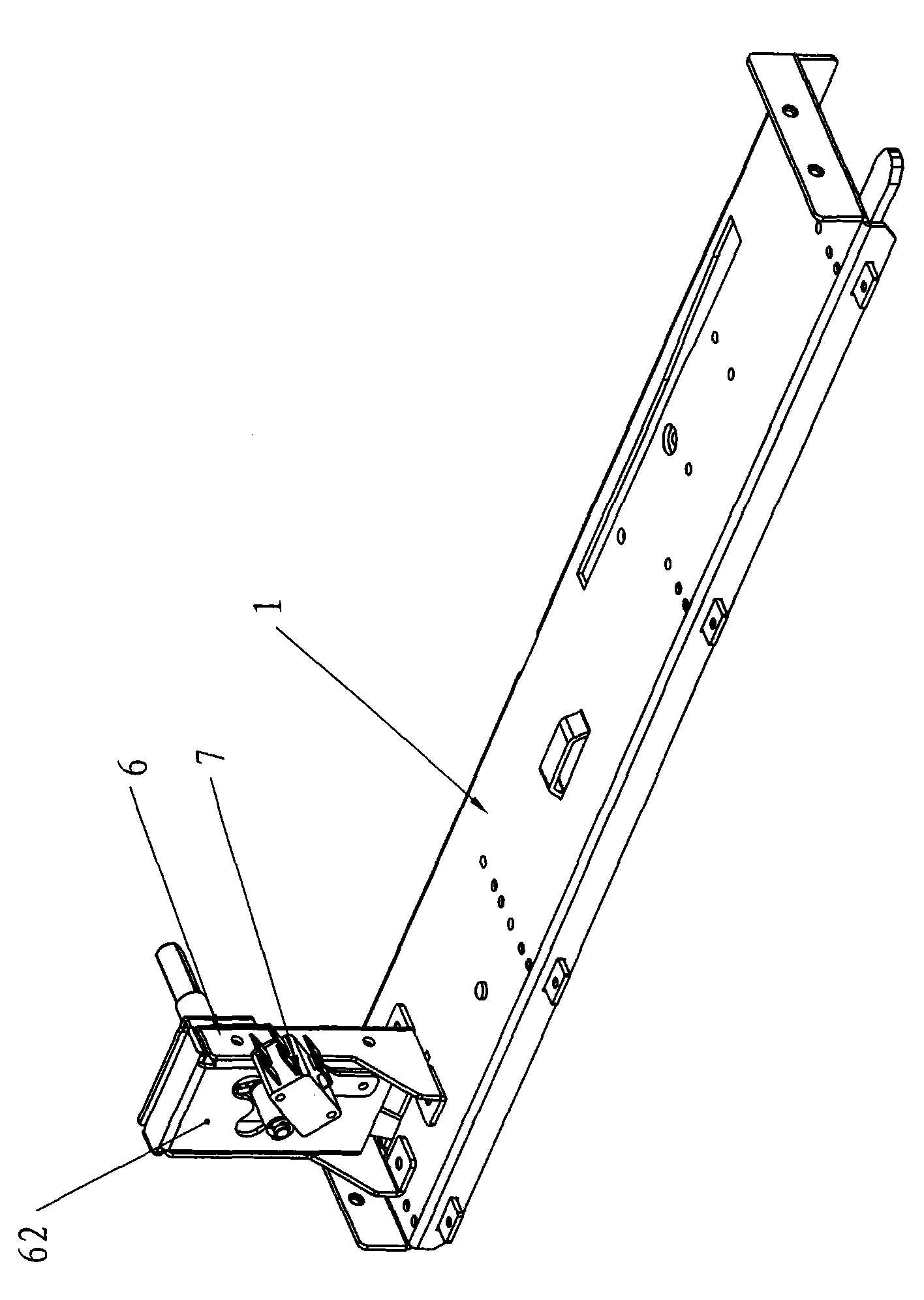
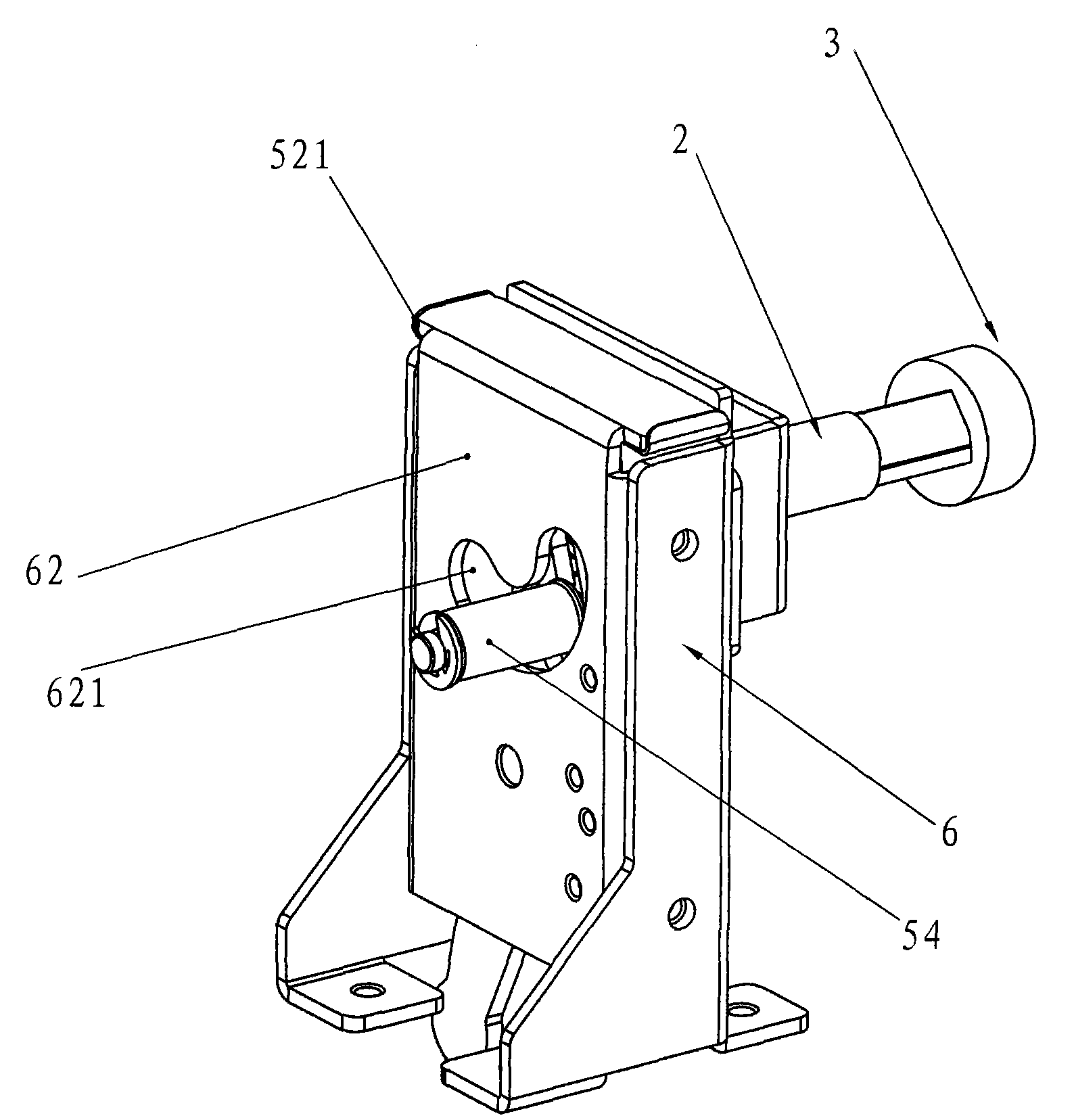
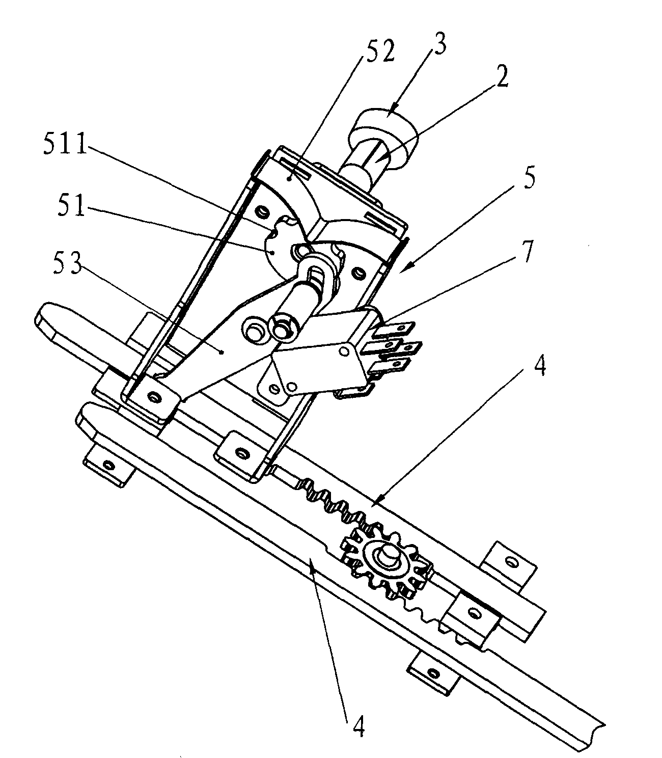
[0016] Such as figure 1 , figure 2 , image 3 , Figure 4 The switch cabinet drawer interlocking mechanism shown includes a rotating shaft 2 pivotally mounted on the drawer body 1, a handle 3 disposed on the rotating shaft 2, and two locking locks with sawtooth pivotally mounted on the drawer body 1. Bar 4, the two locking bars 4 form a relative axial movement through the linkage with the rotating shaft 2. The rotating shaft 2 and the two locking bars 4 are linked through an interlock mechanism 5. The interlock mechanism 5 includes a The transmission block 51, the limit piece 52 that constitutes the multi-position limit of the transmission block 51, the swing arm 53 that is connected with the transmission block 51 and is swinging, and the swing arm 53 is connected with any locking bar 4. In the linkage mechanism 5, the drive block 51 is driven by the rotating shaft 2, and the drive block 51 drives the swing arm 53 to swing, and the swing arm 53 drives the locking bar 4 to ...


PUM


Abstract

The invention relates to a switch cabinet drawer interlocking mechanism and provides the following technical scheme that the switch cabinet drawer interlocking mechanism comprises a revolving shaft, a handle and two locking strips, wherein the spindle is pivoted on a drawer body, the handle is arranged on the revolving shaft, and two locking strips with sawtooth are pivoted on the drawer body andare in linkage with the revolving shaft to form relative axial movement; the revolving shaft and the two locking strips are in linkage by the interlocking mechanism; the interlocking mechanism comprises a driving block, a locating part and a swing arm, wherein the driving block is connected with the revolving shaft, the locating part forms multistation locating of the driving block, and the swingarm is connected with and in swing cooperation with the driving block and is connected with either of the blocking strips. The invention provides the switch cabinet drawer interlocking mechanism withsimple structure and low cost by the above technical scheme.

Description

technical field [0001] The invention relates to a switch cabinet drawer interlocking mechanism. Background technique [0002] At present, the interlocking transmission of the drawers in the switchgear has many forms, such as the interlocking mechanism that is directly pushed and pulled out by hand, which is based on the intermeshing of the gear and the rack installed on the interlocking installation plate and the handle of the control gear through the connecting piece. Control the two saw-toothed locking bars pivotally mounted on the drawer body of the switch cabinet to run relatively axially, so as to lock the drawer in the isolation, test and connection positions. Although this method can lock the drawer and display it in the working position , testing, extraction or other stations, but the use of gear transmission positioning makes the overall volume of the transmission part increase, occupying the installation position of the instrument panel, and the material requiremen...

Claims


Application Information

Patent Timeline
Patent Type & Authority Patents(China)
IPC IPC(8): H02B11/133H02B11/173
Inventor 潘敏潘正东朱明辉
Owner WENZHOU ZHONG YI LOCK ELECTRIC CO LTD
Learn More