Capacitance compensation switch

A switching switch and capacitance compensation technology, which is applied in the direction of reactive power adjustment/elimination/compensation, electrical components, electrical equipment structural parts, etc., can solve the problems of inconvenient installation and maintenance, long lead wires, and susceptibility to external interference, etc. Problems, to achieve the effect of electrical clearance and creepage distance guarantee, simple and beautiful structure, simple and stable structure

Inactive Publication Date: 2010-04-07
JIANGSU MODUN ELECTRIC
View PDF0 Cites 11 Cited by
  • Summary
  • Abstract
  • Description
  • Claims
  • Application Information

AI Technical Summary

Problems solved by technology

[0002] Existing thyristor switches are of the exposed type, that is, both the thyristor components and the heat sink are exposed to the outside. Under such working conditions, these devices are easily subject to external interference and cause false triggering of the thyristor, and The protection performance is poor, and the operator is easy to touch during the installation and debugging process, causing personal safety accidents such as electric shock, so people consider adding a shell, but the installation of the shell and the heat dissipation base has problems such as unstable installation and lack of closeness; some The thyristor switch has a small terminal block or even no terminal block, which makes it very inconvenient for the operator to connect during installation and use. With a small terminal block, it is easy to touch the line connection. , causing a short circuit, which will affect the reliability and service life of the entire device. For the case of no terminal block, the connection of the thyristor needs to be connected to a place far from the thyristor switch, so that not only the wire needs The drag is very long, resulting in waste, and the middle distance is long, it is easy to be interfered by the outside world, thereby reducing the reliability of the switch; the circuit board installation of the existing thyristor switch has a complicated structure and high cost, and the control circuit board is placed on hold. It is inconvenient for installation and maintenance if it is placed in a remote place or embedded between thyristor components. It is difficult to guarantee its electrical clearance and creepage distance, and the work of the control circuit board will be affected. false triggering of

Method used


Image

  • Capacitance compensation switch
  • Capacitance compensation switch
  • Capacitance compensation switch

Examples


Embodiment Construction

[0033] The present invention will be described in further detail below in conjunction with the accompanying drawings.

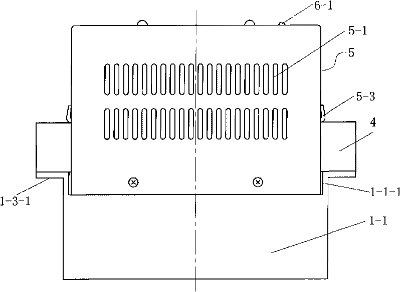
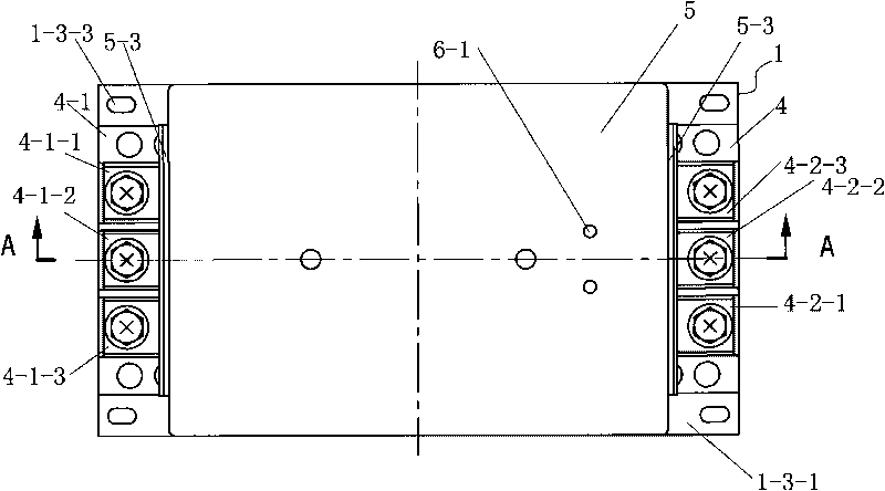
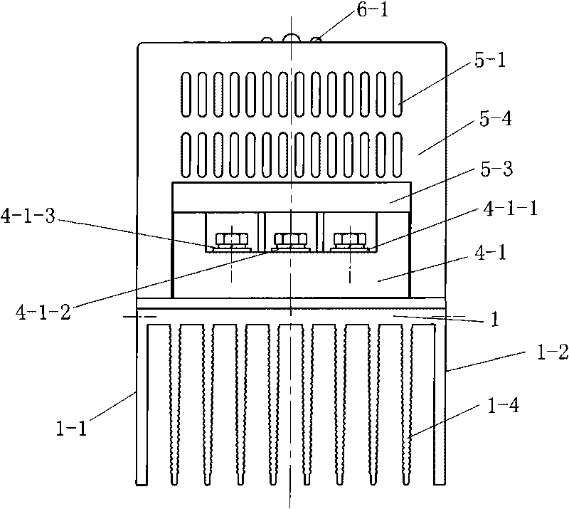
[0034] Such as Figure 1-12, 13-15, and 17, a capacitance compensation switching switch includes a heat dissipation base 1, a thyristor module 3, a terminal block 4, a casing 5 and a control circuit board 6, and the thyristor module 3 is installed on On the heat dissipation base 1 and located in the shell 5, the control circuit of the control circuit board 6 has a signal input end and a signal output end, and the signal output end of the control circuit is electrically connected with the control end of the thyristor module 3, and the heat dissipation base 1 has a heat dissipation substrate 1-3 and the first side plate 1-1 at the lower part of both sides, the second side plate 1-2 and the heat sink 1-4 at the lower part of the middle, and the heat sink 1-4 is connected with the first side plate 1-1 and the second side plate 1-2 are arranged in parallel; the f...


PUM


Abstract

The invention provides a capacitance compensation switch. A silicon controlled module is installed on a heat dissipation base and is arranged in a casing; the control circuit on a control circuit board is provided with a signal input end and a signal output end; the signal input end of the silicon controlled module is electrically connected with the signal output end of the control circuit; the heat dissipation base is provided with a heat dissipation base plate and two side plates and heat dissipation fins; the heat dissipation fins and the two side plates are arranged in parallel; the two ends of the heat dissipation base plate is provided with a protrusion part which is provided with an installation through hole; the side plate of the heat dissipation base plate is provided with an installation groove which is provided with installation screw holes; the lower part of the side plate of the casing is inserted into the installation groove and is fixedly connected onto the side plate through screws and installation screw holes; two connecting terminal rows are installed on the heat dissipation base plates; the silicon controlled module is arranged between the two connecting terminal rows; the controlled silicon module and the connecting terminal rows are electrically connected through an electric conductor; and the control circuit board is installed on the inner wall of the top plate of the casing. The invention has simple and stable structure, convenient installation, easy maintenance, little electromagnetic interference and high reliability.

Description

technical field [0001] The invention relates to the field of switches, in particular to a capacitance compensation switching switch. Background technique [0002] Existing thyristor switches are of the exposed type, that is, both the thyristor components and the heat sink are exposed to the outside. Under such working conditions, these devices are easily subject to external interference and cause false triggering of the thyristor, and The protection performance is poor, and the operator is easy to touch during the installation and debugging process, causing personal safety accidents such as electric shock, so people consider adding a shell, but the installation of the shell and the heat dissipation base has problems such as unstable installation and lack of closeness; some The thyristor switch has a small terminal block or even no terminal block, which makes it very inconvenient for the operator to connect during installation and use. With a small terminal block, it is easy ...

Claims


Application Information

Patent Timeline
Patent Type & Authority Applications(China)
IPC IPC(8): H02J3/18H05K7/20
CPCH05K7/209
Inventor 戴志勇陆伯帅
Owner JIANGSU MODUN ELECTRIC
Why Eureka
Try Eureka