Counter-flow flame combustion chamber

A combustor and flame technology, applied in the field of aviation gas turbine combustor, can solve the problems of inability to meet the low pollution requirements of the engine, high CO and UHC emissions, uneven local equivalence ratio, etc., and achieve fast and stable combustion, low pollution emissions, and high efficiency. The effect of stable work

Inactive Publication Date: 2010-04-14
BEIHANG UNIV
View PDF0 Cites 22 Cited by
  • Summary
  • Abstract
  • Description
  • Claims
  • Application Information

AI Technical Summary

Benefits of technology

In this new type of internal combustions (IC) engines, there have been improvements over previous designs such as having multiple rings or cylindrical spaces inside it for better heat distribution during operation. These modifications aim at improving efficiency without increasing exhaust emission levels. Additionally, they allow for more efficient use of space due to their unique shape. Overall these technical benefits improve performance and reduce environmental impact caused by harmful gases released into our environment through IC engines.

Problems solved by technology

Technological Problem addressed in this patents relates to reducing nitrous gas (NO2) production from aircraft engines while also meeting stricter regulations such as exhaust particulate control devices or diesel generators. Current solutions involve developing better catalyst systems without causing harmful effects like increased smoke levels and reduced efficiency. However, these improvements may result in decreased temperatures near certain limits during operation, leading to incomplete reduction of specific components called N0X. Therefore, an improved solution needs to address both issues simultaneously including improving greenhouse effectiveness and achieving evenness of fuel injection flow over areas where they occur frequently.

Method used


Image

  • Counter-flow flame combustion chamber
  • Counter-flow flame combustion chamber
  • Counter-flow flame combustion chamber

Examples


Embodiment Construction

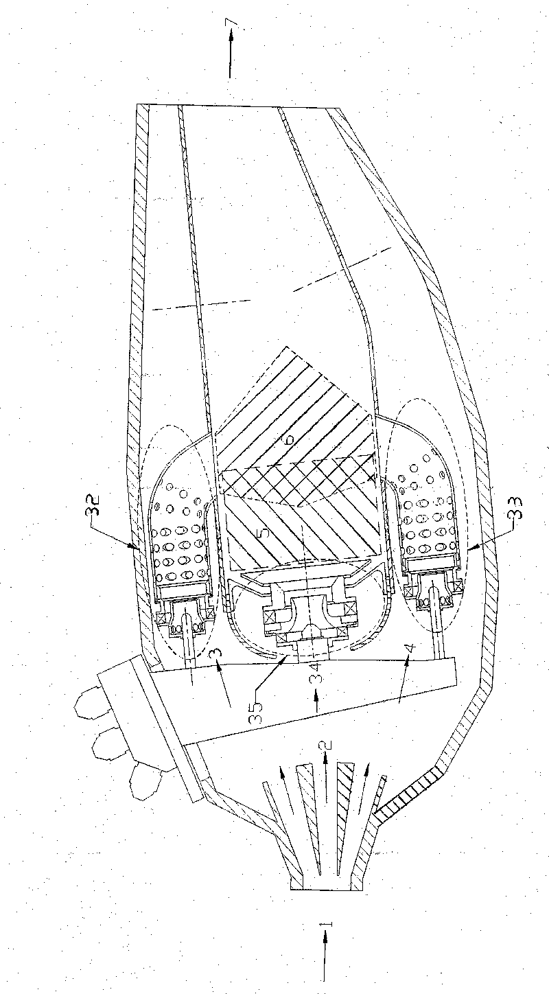
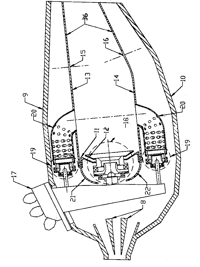
[0026] Such as figure 1 with figure 2 As shown, the opposing flame combustion chamber designed by the present invention has a single-ring cavity structure, and adopts the concept design of staged combustion. Organization mode, the main combustion stage adopts the combustion organization mode of premixed pre-evaporation combined with opposing flames, and the cooling gas and mixed gas are supplied from the flame tube. The combustion chamber includes two combustion areas—the head pre-combustion level combustion area 5 and the opposing flame main combustion level combustion area 6. The two combustion areas share the same inner and outer boundaries. The outer boundary of the combustion area is the outer wall 13 of the flame tube. The inner boundary of the area is the inner wall 14 of the flame tube, and the outer wall 13 of the annular flame tube and the inner wall 14 of the flame tube are located between the annular casing 9 outside the combustion chamber and the casing 10 insid...


PUM


Abstract

The invention relates to a counter-flow flame combustion chamber which has a monocyclic cavity structure. The counter-flow flame combustion chamber is designed by adopting a concept of staged combustion, and combustion gas is supplied from a pre-combustion stage and a main combustion stage, wherein the pre-combustion stage adopts a diffusion combustion structural mode with stable whirlblast, and the main combustion stage adopts a combustion structural mode of combining premixing and pre-evaporation with counter-flow flame. The counter-flow flame combustion chamber mainly comprises a shunt diffuser, an external combustion chamber case shell, an internal combustion chamber case shell, a fuel nozzle, a head pre-combustion stage, a flame tube external wall main combustion stage, a flame tube internal wall main combustion stage, a flame tube external wall and a flame tube internal wall, wherein the head pre-combustion stage utilizes stable flame in a low-speed backflow area, which is generated by whirlblast air entering the combustion chamber from a pre-combustion stage whirlblast assembly; the main combustion stage comprises the flame tube internal wall main combustion stage and the flame tube external wall main combustion stage, and uniform oil-gas mixture jetted from the main combustion stage counters in a flame tube to form a counter jet flow which forms counter-flow flame under the ignition of pre-combustion flame. The invention has simple structure, and can effectively reduce disposal of pollutants besides ensuring the normal work condition of an aeroengine.

Description


Claims


Application Information

Patent Timeline
Owner BEIHANG UNIV
Why Eureka
Try Eureka