Phase shifter

A phase shifter and metal cavity technology, applied in the field of phase shifters, can solve the problems of large loss, inability to control the phase of the radiation unit, and high cost, and achieve the effects of low cost, simple structure, and convenient phase control.

Inactive Publication Date: 2010-04-14
ROSENBERGER (SHANGHAI) TECH CO LTD
View PDF2 Cites 26 Cited by
  • Summary
  • Abstract
  • Description
  • Claims
  • Application Information

AI Technical Summary

Problems solved by technology

[0003] U.S. Patents US7463190 and US6850130 respectively disclose an integrated phase shifter with one input terminal and multiple output terminals. These two phase shifters all use a moving mechanism to achieve the phase change of multiple output terminals. These output terminals are connected through cables. Connected to the radiating unit, so as to control the phase change of the radiating unit and change the inclination angle of the antenna radiation beam. However, when the number of radiating units is greater than the number of output ports of the phase shifter, the above-mentioned phase shifter cannot control the phase of each radiating unit. The radiating elements are fed in groups, so the performance of the antenna array is limited. At the same time, both phase shifters use expensive printed circuit boards, which are very costly and lossy

Method used


Image

  • Phase shifter
  • Phase shifter
  • Phase shifter

Examples


Embodiment Construction

[0016] Embodiments of the present invention will be described in detail below in conjunction with the accompanying drawings.

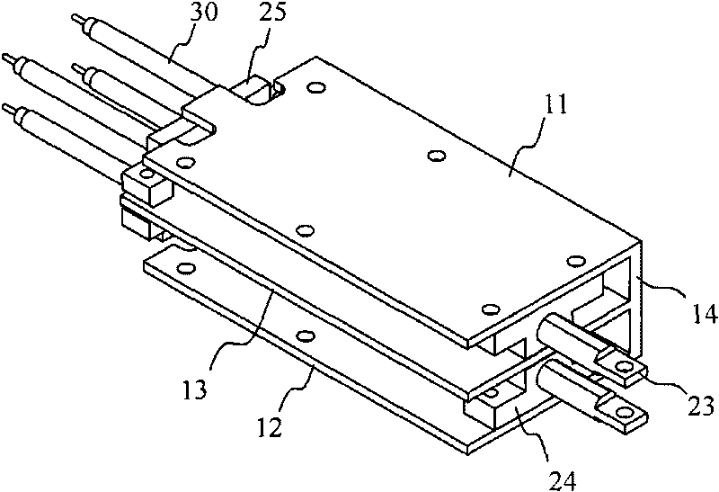
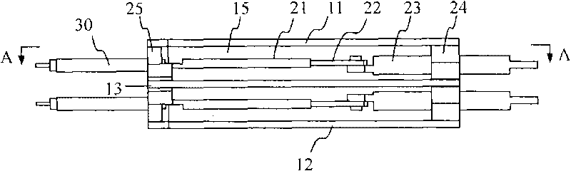
[0017] figure 1 It is a three-dimensional schematic diagram of an embodiment of the phase shifter of the present invention, figure 2 for figure 1 main view of image 3 for figure 2 A-A sectional view of the middle phase shifter, Figure 4 for figure 1 left view of . Such as Figure 1~4 As shown, the phase shifter of the present invention includes a metal cavity, and the metal cavity is composed of an upper cover plate 11, a lower bottom plate 12 and a side plate 14, and the metal cavity is divided into two chambers by a partition 13 15. The upper cover plate 11, the lower bottom plate 12, the side plate 14 and the partition plate 13 of the metal cavity can be integrally formed, such as by casting, to meet the requirements of mass production. Of course, the various parts of the metal cavity and the partition plate 13 can also be fixedly conne...


PUM


Abstract

The invention discloses a phase shifter, which comprises a metal cavity body. The metal cavity body comprises an upper cover plate, a lower bottom plate and a lateral plate, the inside of the metal cavity body is divided into pluralities of cavities through partition boards, two parallel metal conductive cylinders and a U-shaped metal conductor are arranged inside each cavity of the metal cavity body, two free ends of one U-shaped metal conductor are respectively inserted into the two metal conductive cylinders; the U-shaped metal conductor is connected with an insulating pull rod which is positioned via an insulation guide part, the insulation pull rod drives each U-shaped metal conductor to move leftwards and rightwards correspondingly to the metal conductive cylinders; the insulation guide part is fixedly connected with the metal cavity body; the two metal guide cylinders are respectively connected with coaxial cables. The phase shifter enables phase control of each radiation unit to be extremely convenient, and has simple structure and low cost.

Description

technical field [0001] The invention relates to an antenna component, in particular to a phase shifter for a base station antenna. Background technique [0002] In addition to the radiation unit, reflector, and feed network, the phase shifter is an important part of the phased antenna. The phase shifter is mainly used in the base station antenna to adjust the phase change of the feed network, so as to change the phase of each or a group of radiating elements, and achieve the purpose of changing the vertical beam inclination or horizontal beam angle, which is a wireless network. Operators provide more flexible optimization means to optimize the performance of the entire system. [0003] U.S. Patents US7463190 and US6850130 respectively disclose an integrated phase shifter with one input terminal and multiple output terminals. These two phase shifters all use a moving mechanism to achieve the phase change of multiple output terminals. These output terminals are connected thro...

Claims


Application Information

Patent Timeline
Patent Type & Authority Applications(China)
IPC IPC(8): H01P1/18
CPCH01P1/183H01P5/10
Inventor 邓刚毅陈聪徐韩兴徐东良
Owner ROSENBERGER (SHANGHAI) TECH CO LTD
Why Eureka
Try Eureka