Electromagnetic tomography nondestructive inspection device for severe fault of rail and method thereof

A non-destructive testing, electromagnetic layer technology, applied in the direction of material magnetic variables, etc., can solve problems such as failure to achieve the depth and location of rail damage, small detection range, and detection.

Inactive Publication Date: 2011-05-04
BEIJING JIAOTONG UNIV
View PDF6 Cites 0 Cited by
  • Summary
  • Abstract
  • Description
  • Claims
  • Application Information

AI Technical Summary

Problems solved by technology

[0002] At present, the technology that can be used for high-speed online rail flaw detection is electromagnetic rail flaw detection, but the electromagnetic rail flaw detection technology is a point measurement mode. Due to the limitation of its principle, its detection range is only 5% to 30% of the rail head
Although the detection range of electromagnetic rail flaw detection is small, in the current situation where high-speed rail detection is urgently needed, this technology still has obvious advantages due to its non-contact and high-speed characteristics, but it has not yet achieved the accuracy of rail damage depth and position. detection

Method used


Image

  • Electromagnetic tomography nondestructive inspection device for severe fault of rail and method thereof
  • Electromagnetic tomography nondestructive inspection device for severe fault of rail and method thereof
  • Electromagnetic tomography nondestructive inspection device for severe fault of rail and method thereof

Examples


Embodiment Construction

[0014] Embodiments of the present invention are described in detail below in conjunction with the accompanying drawings:

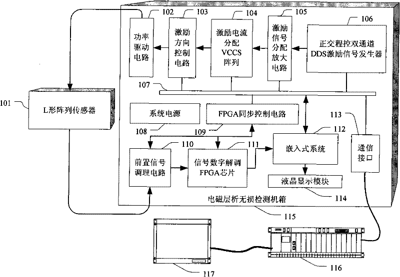
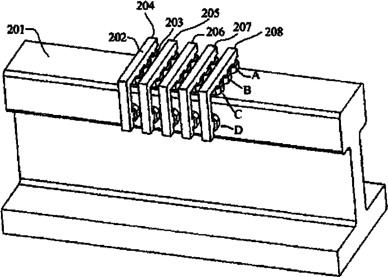
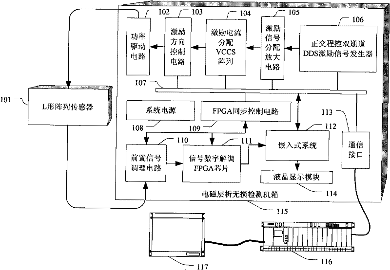
[0015] Electromagnetic tomography non-destructive testing device for severe rail damage according to the present invention, such as figure 1 As shown, it includes an L-shaped array sensor 101 , an electromagnetic tomography nondestructive testing case 115 , a flaw detection monitoring and recording computer 116 , and a flaw detection monitoring liquid crystal panel 117 .

[0016] Among them, the electromagnetic tomography nondestructive testing chassis 115 includes a power drive circuit 102, an excitation direction control circuit 103, an excitation current distribution VCCS array 104, an excitation signal distribution amplification circuit 105, and an orthogonal program-controlled dual-channel DDS (Direct Digital Dynthesizer, direct frequency synthesizer ) excitation signal generator 106, bus 107, system power supply 108, FPGA synchronous control circuit ...


PUM


Abstract

The invention provides an electromagnetic tomography nondestructive inspection device for severe fault of a rail and a method thereof. The inspection device comprises an L-shaped array sensor, an electromagnetic tomography nondestructive inspection case, a fault detection monitoring and recording computer and a fault detection monitoring liquid crystal panel, wherein the electromagnetic tomography nondestructive inspection case comprises a power driving circuit, an excitation direction control circuit, an excitation current distribution VCCS array, an excitation signal distribution amplification circuit, an orthogonal program control two-channel DDS excitation signal generator, a bus, a system power supply, an FPGA synchronous control circuit, a preposed signal conditioning circuit, a signal digital demodulation FPGA chip, an embedded system, a communication interface and a liquid crystal display module. The device and the method can ensure on-line inspection of rail fault inspection along with train operation, and is convenient for discovering the condition of serious fault of the rail with severe potential danger to rail transportation in time.

Description

technical field [0001] The invention relates to a non-destructive detection device and method of electromagnetic tomography for severe rail damage. Background technique [0002] At present, the technology that can be used for high-speed online rail flaw detection is electromagnetic rail flaw detection, but the electromagnetic rail flaw detection technology is a point measurement mode. Due to the limitation of its principle, its detection range is only 5% to 30% of the rail head. Although the detection range of electromagnetic rail flaw detection is small, in the current situation where high-speed rail detection is urgently needed, this technology still has obvious advantages due to its non-contact and high-speed characteristics, but it has not yet achieved the accuracy of rail damage depth and position. detection. Contents of the invention [0003] The purpose of the present invention is to provide a non-destructive detection device and method of electromagnetic tomograph...

Claims


Application Information

Patent Timeline
Patent Type & Authority Patents(China)
IPC IPC(8): G01N27/82
Inventor 刘泽张晓飞韦钟辉
Owner BEIJING JIAOTONG UNIV
Why Eureka
Try Eureka