Switch component

A technology of switch components and parts, which can be used in electrical switches, electrical components, contacts, etc., to solve problems such as poor contact

Active Publication Date: 2012-01-11
SHANGHAI BAICHENG ELECTRONICS
View PDF4 Cites 0 Cited by
  • Summary
  • Abstract
  • Description
  • Claims
  • Application Information

AI Technical Summary

Problems solved by technology

[0008] For example, it is an object of the present invention to solve the problem of poor contact at the pivotal connection between the pivotal contact lever and the support in conventional switches

Method used


Image

  • Switch component
  • Switch component
  • Switch component

Examples


Embodiment 1

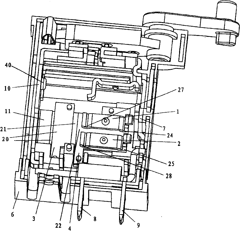
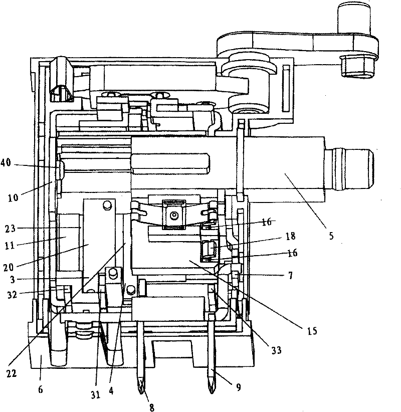
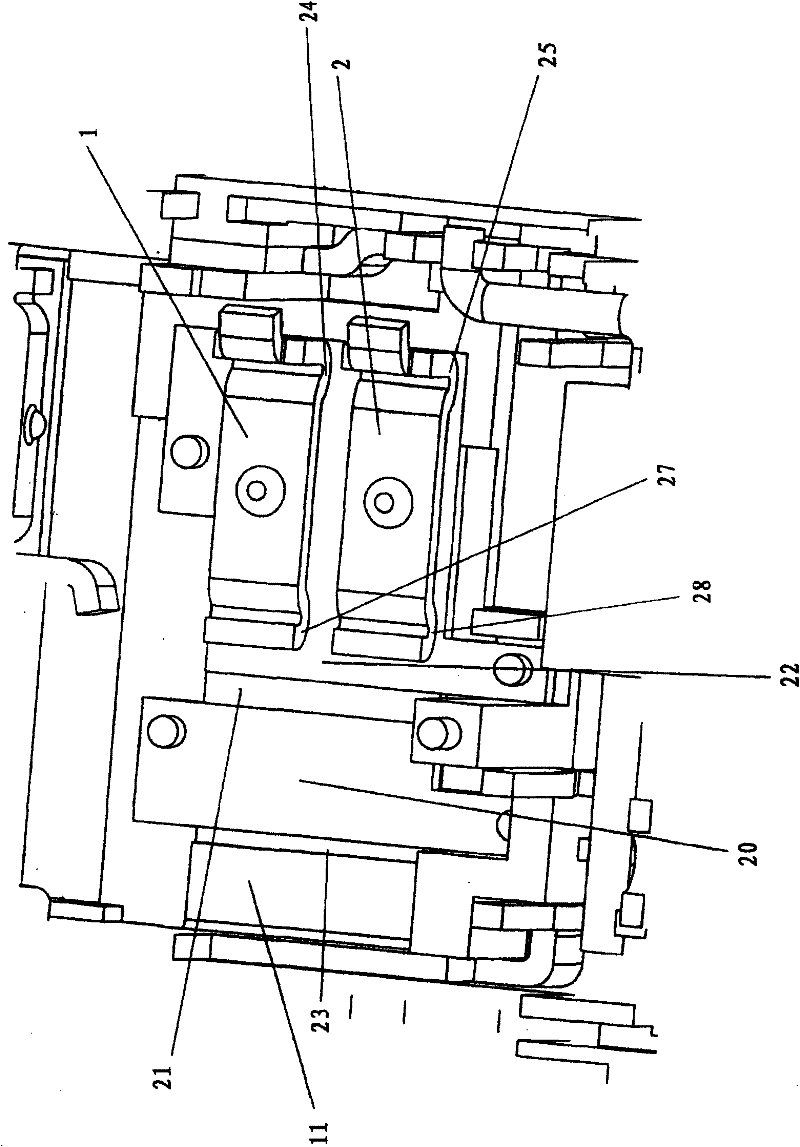
[0210] Figure 1-20 as well as Figure 77 A first embodiment of the invention is shown. Such as Figure 1-3 , 13-15 and 18-19, the switch assembly according to this embodiment includes a housing 6. The housing 6 is equipped with a power negative input fixed contact part 4 as an input part and a power positive input fixed contact part 7 as another input part. Both the power negative input fixed contact part 4 and the power positive input fixed contact part 7 with the power negative input fixed contact piece 22 are fixed on the housing 6 . One end 8 of the negative pole input fixed contact part 4 of the power supply is used for electrical connection with the negative pole of the power supply. One end 9 of the positive input fixed contact part 7 of the power supply is used for electrical connection with the positive pole of the power supply. A straight-through fixed contact part 10 is also fixed on the housing 6 . Especially as Figure 11 As shown, the through-fixed contact...

Embodiment 1

[0224] Embodiment 1 adopts the contact method of double sliding contact pieces, that is, from the start of work to the speed regulation state, and then to the straight-through state, two same sliding contact pieces are used, that is, all the working contact surfaces are double. Compared with products using single sliding contact sheet moving contact, this product adds a current channel during operation, which reduces the current flowing through each current channel, reduces the total contact resistance, and improves the current carrying capacity of the switch. It will increase accordingly.

Embodiment 2

[0226] Figure 21-46 The second embodiment of the present invention is shown. The main difference between embodiment 2 and embodiment 1 is that in embodiment 1, the through function of the switch is through the sliding contact pieces 1 and 2 and the power supply negative input fixed contact piece 22 at the same time It is realized by contacting with the straight-through fixed contact piece 11 on the straight-through fixed contact part 10 . And in embodiment 2, straight-through fixed contact piece 11 is not provided with through-through fixed contact piece 211 on the straight-through fixed contact part 10, and the sliding contact piece is still contacted with speed-regulating fixed contact piece in the rear part of the stroke of push rod or It may not be in contact with the speed regulating fixed contact piece, but it must not be in contact with the straight-through fixed contact part. The through function of the switch is realized by at least two pivoting contact parts connec...


PUM


Abstract

The invention particularly relates to a switch and is used to improve the structure at the contact part used for turning on and off in a switch to reduce current in each contact point and total contact resistance. The problem of poor contact at the pin joint position of a pin joint contact rod and a supporting part in the conventional switch is solved by arranging an additional elastic metal plate on the pin joint contact rod. Due to the contact part arranged on a rotary contact device at the position of a forward / reverse conversion mechanism, the total contact area is increased, current in each contact point is further reduced, and the total contact resistance and heat generation between the rotary contact device at the position of the forward / reverse conversion mechanism and an internalinput and an external output are reduced.

Description

[0001] This application is a divisional application of an invention patent application named "Switch Assembly", application number: 200610002402.0, and application date January 27, 2006. technical field [0002] The invention relates to an electrical switch assembly. It also relates to a high power DC switch, more particularly to a trigger switch for trigger control of a power tool. Background technique [0003] A Marquardt (Trademark) type 2711.5507 high power DC switch is already known in the art with a power of 18V DC 25A. US6717080B1 discloses a trigger switch assembly for a power tool with an electric motor. US6741051B2 discloses a trigger controller for a power tool including an electric motor. US6104105 also discloses an electrical switch for turning on or off a tool with an electric motor. US6794594 discloses a trigger switch assembly for controlling electric tools. The applicant himself has sold switch assemblies for controlling power tools as well as various ot...

Claims


Application Information

Patent Timeline
Patent Type & Authority Patents(China)
IPC IPC(8): H01H1/58H01H1/50
Inventor 徐新生
Owner SHANGHAI BAICHENG ELECTRONICS
Why Eureka
Try Eureka