
Two-stage circulation and two-stage water distribution heat supply device

A water floor heating and water supply device technology, applied in hot water central heating system, household heating, space heating and ventilation details, etc., can solve the problems that the temperature of each room cannot be controlled independently, and the temperature of large rooms is uneven, and achieve structural Rigorous, uniform heating temperature, good energy-saving effect

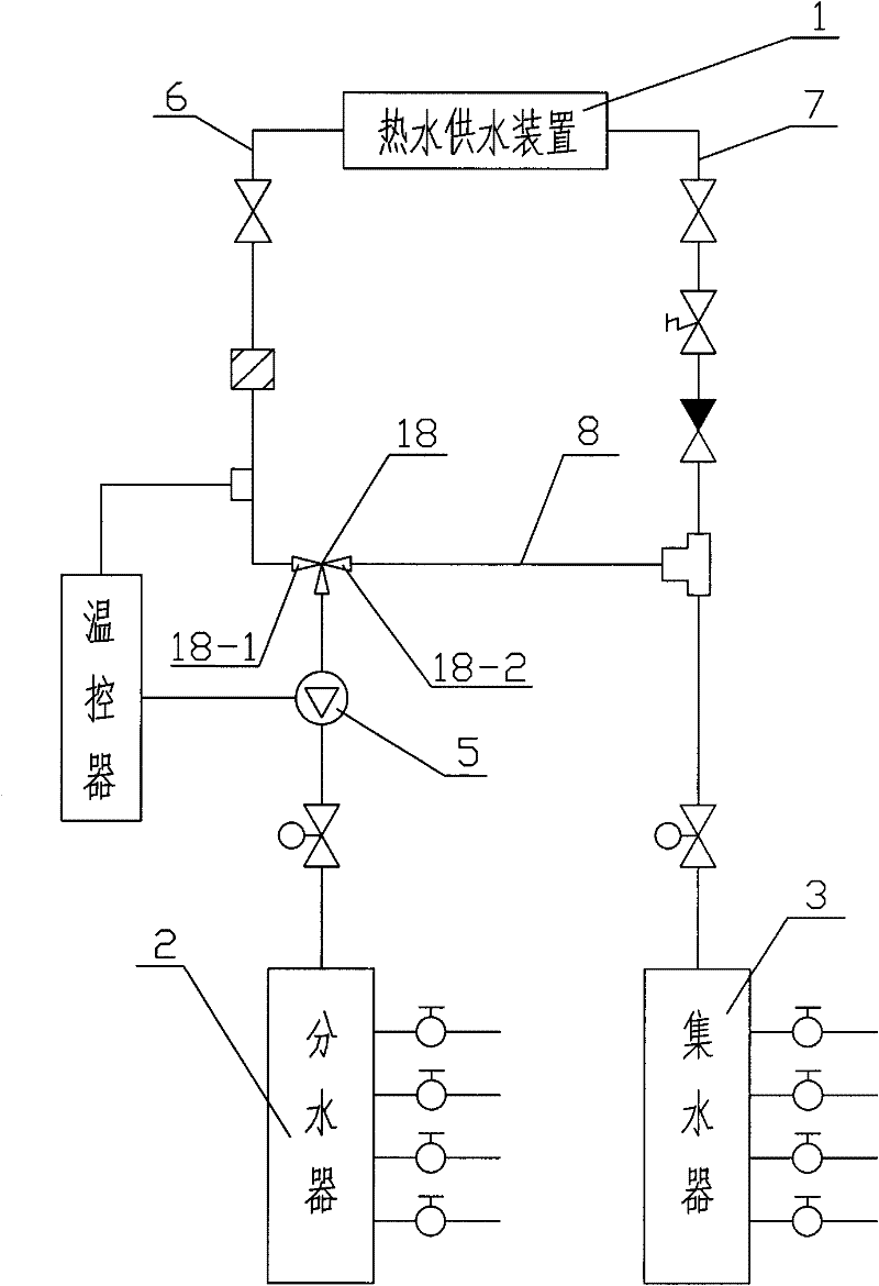
Inactive Publication Date: 2012-08-22
林峰
View PDF3 Cites 0 Cited by
  • Summary
  • Abstract
  • Description
  • Claims
  • Application Information

AI Technical Summary

Problems solved by technology

[0005] The purpose of the present invention is to provide a two-stage circulation and two-stage water separation floor heating device to overcome the defects in the prior art such as uneven temperature in large rooms and inability to control the temperature of each room independently.

Method used


Image

  • Two-stage circulation and two-stage water distribution heat supply device
  • Two-stage circulation and two-stage water distribution heat supply device
  • Two-stage circulation and two-stage water distribution heat supply device

Examples


Embodiment Construction

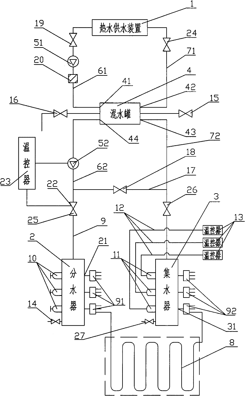
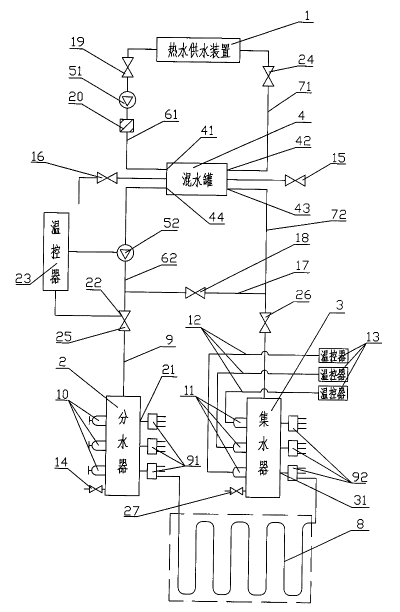
[0019] see figure 2 As shown, the present invention is a two-stage circulation and two-stage water separation floor heating device, which mainly consists of a hot water supply device 1, a water separator 2, a water collector 3, a water mixing tank 4, a first circulation pump 51, and a second circulation pump 52 , water supply pipe 61, water supply pipe 62, return water pipe 71, return water pipe 72, flow regulating valve 10, electrothermal actuator 11 and N groups of floor heating coils 8. The hot water supply device 1 forms a first circulation through the water supply pipe 61 , the first circulating pump 51 , the first inlet 41 of the mixing tank, the first outlet 42 of the mixing tank and the return pipe 71 . The second circulating pump 52, the water separator 2, the N groups of ground coils 8, the water collector 3, the second inlet 43 of the mixing tank, the second outlet 44 of the mixing tank, and the water supply pipe 62 and return pipe connecting the above-mentioned co...


PUM


Abstract

The invention relates to a two-stage circulation and two-stage water distribution heat supply device, comprising a hot water supply device, a water distributor, a water collector, a water mixing tank, a circulating pump, a water supply pipe, a water return pipe, N sets of heat supply coiled tubes, a two-stage water distributor and a two-stage water collector. The hot water supply device forms a circulation through the water supply pipe, the circulating pump, a first inlet of the water mixing tank, a first outlet of the water mixing tank and the water return pipe; and the circulating pump, thewater distributor and two-stage water distributor thereof, the N sets of heat supply coiled tubes, the water collector and two-stage water collector thereof, a second inlet of the water mixing tank, a second outlet of the water mixing tank, the water supply pipe and the water return pipe form a second circulation. The invention has the advantages of being convenient to control the water supply temperature output by the water distributor, ensuring that the temperature for water supply does not exceed the design requirements of the heat supply coiled tubes, prolonging the service life of the heat supply coiled tubes, meeting independent temperature control requirement of various rooms and ensuring that the heating temperature of large-area rooms is uniform and the temperatures of a plurality of rooms can be independently controlled. The whole system has simple structure, convenient operation and favorable energy-saving effect.

Description

technical field [0001] The invention relates to a heating system, in particular to a two-stage circulation and two-stage water-dividing floor heating device circulating by a pump. Background technique [0002] Ground radiation heating with low-temperature hot water, referred to as floor heating, is an energy-saving heating system gradually developed at home and abroad in recent years. It uses low-temperature hot water as the heat source, the floor as the heating body, and mainly uses radiation heat transfer, supplemented by convective heat transfer, to adjust the thermal microclimate of the room. It has the advantages of uniform heat dissipation, no room space, energy saving, and small maintenance. [0003] In the prior art, utility model patent No. ZL200720001055.X discloses a floor heating water circulation temperature control device. cycle. The hot water supply device 1 is connected to the water distributor 2 through the water supply pipe 6 to provide hot water for the...

Claims


Application Information

Patent Timeline
Patent Type & Authority Patents(China)
IPC IPC(8): F24D3/12F24D3/02F24D3/10F24D19/10F24D19/08
CPCY02B30/00
Inventor 林峰
Owner 林峰
Learn More