Air and air energy recovery and ventilation device with defrosting and bypass air supplying functions
A technology of energy recovery and ventilation device, which is applied in space heating and ventilation, ventilation system, heating and ventilation control system, etc., can solve the problem that the effect of cooling capacity to eliminate indoor load is not utilized, and improve the operation time of the whole year. , Improve the efficiency of use and reduce the effect of recycling years
- Summary
- Abstract
- Description
- Claims
- Application Information
AI Technical Summary
Problems solved by technology
Method used
Image
Examples
specific Embodiment approach 1
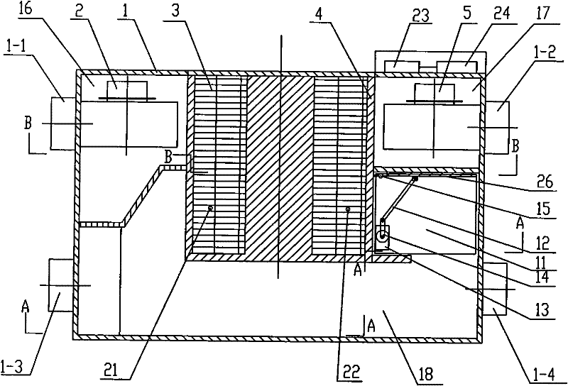
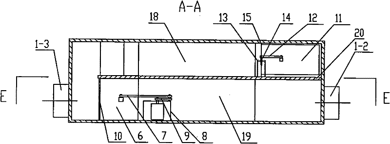
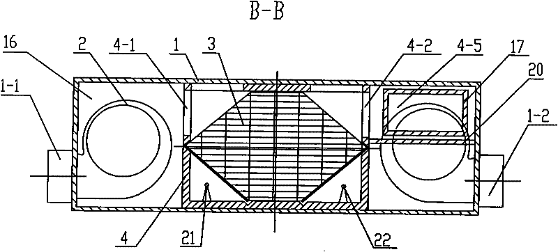
[0007] Specific implementation mode one: combine Figure 1-Figure 6 Describe this embodiment, the air and air energy recovery ventilation device of this embodiment includes a casing 1, an exhaust fan 2, a heat exchanger 3, a heat exchanger frame 4, a fresh air fan 5, and a bypass defrosting damper 6 and a power controller 24, the heat exchanger frame 4 is fixedly connected to the top surface, the left inner wall and the right inner wall of the casing 1, and the heat exchanger frame 4 divides the casing 1 into an exhaust chamber 16, Fresh air chamber 17, bypass air supply passage 18 and bypass defrosting air passage 19, the heat exchanger 3 is installed in the heat exchanger frame 4, and a side wall 4-6 of the heat exchanger frame 4 is provided with There is an exhaust vent 4-1 and a first air passage 4-3, and the other side wall 4-7 of the heat exchanger frame 4 is provided with a fresh air vent 4-2 and a second air passage 4-4, the exhaust fan 2 is installed in the exhaust c...
specific Embodiment approach 2
[0008] Specific implementation mode two: combination Figure 1-Figure 6 Describe this embodiment, the bypass defroster damper 6 of this embodiment is constituted by the first connecting rod 7, the first motor 8, the first slider 9, the first hinge 10 and the first baffle 25, the first A baffle plate 25 is arranged at the fresh air inlet 1-3 and is hinged with the casing 1 through the first hinge 10, one end of the first connecting rod 7 is hinged with the first baffle plate 25, and the other end of the first connecting rod 7 is hinged with the first connecting rod 7. A slider 9 is hinged, the first slider 9 is connected to the output shaft of the first motor 8, the first motor 8 is fixed on the bottom surface of the casing 1, and the power controller 24 is connected to the first motor through a wire. 8 connections. The first slider 9 is driven by the first motor 8 to rotate, and then drives the first connecting rod 7 to move, and the first connecting rod 7 drives the first ba...
specific Embodiment approach 3
[0009] Specific implementation mode three: combination Figure 7-Figure 12 Describe this embodiment, the air and air energy recovery ventilation device of this embodiment also includes fresh air temperature and humidity sensor 21, exhaust air temperature and humidity sensor 22 and temperature and humidity collection controller 23, and described fresh air temperature and humidity sensor 21 and described exhaust air The temperature and humidity sensor 22 is arranged in the heat exchanger frame 4, the temperature and humidity acquisition controller 23 is fixed on the top outer wall of the casing 1, the fresh air temperature and humidity sensor 21 and the exhaust air temperature and humidity sensor 22 are respectively It is connected to the temperature and humidity acquisition controller 23 through wires, and the temperature and humidity acquisition controller 23 is connected to the power controller 24 through wires. Such a design enables the present invention to automatically swi...
PUM
 Abstract
Description
Claims
Application Information
 - R&D
- Intellectual Property
- Life Sciences
- Materials
- Tech Scout
- Unparalleled Data Quality
- Higher Quality Content
- 60% Fewer Hallucinations
Browse by: Latest US Patents, China's latest patents, Technical Efficacy Thesaurus, Application Domain, Technology Topic, Popular Technical Reports.
© 2025 PatSnap. All rights reserved.Legal|Privacy policy|Modern Slavery Act Transparency Statement|Sitemap|About US| Contact US: help@patsnap.com


