
Method for detecting junction temperature of chip of LED lamp

A technology of LED lamps and chips, applied in thermometers, measuring devices, measuring heat, etc., can solve problems such as difficult measurement of a single chip

Inactive Publication Date: 2010-05-05
SHANGHAI INST OF TECHNICAL PHYSICS - CHINESE ACAD OF SCI
View PDF0 Cites 36 Cited by
  • Summary
  • Abstract
  • Description
  • Claims
  • Application Information

AI Technical Summary

Problems solved by technology

This is mainly because the light source module of the LED lamp is a multi-chip series-parallel structure and the lamp has a unified heat dissipation system, which makes it very difficult to measure a single chip in the lamp under normal working conditions.

Method used


Image

  • Method for detecting junction temperature of chip of LED lamp
  • Method for detecting junction temperature of chip of LED lamp

Examples


Embodiment

[0016] Embodiment: under the measurement room temperature, operating current is I H =2.8A, the chip junction temperature of a 75W LED lamp.

[0017] 1. The hardware system of this measurement method includes Keithley SMU2430, oven, DC power supply, PT100 platinum resistance thermometer, and Agilent 34970A inspection instrument;

[0018] 2. Paste a PT100 platinum resistor with silicone rubber on the bottom of the heat sink of the LED lamp under test, and connect the platinum resistor to the input interface of the inspection instrument;

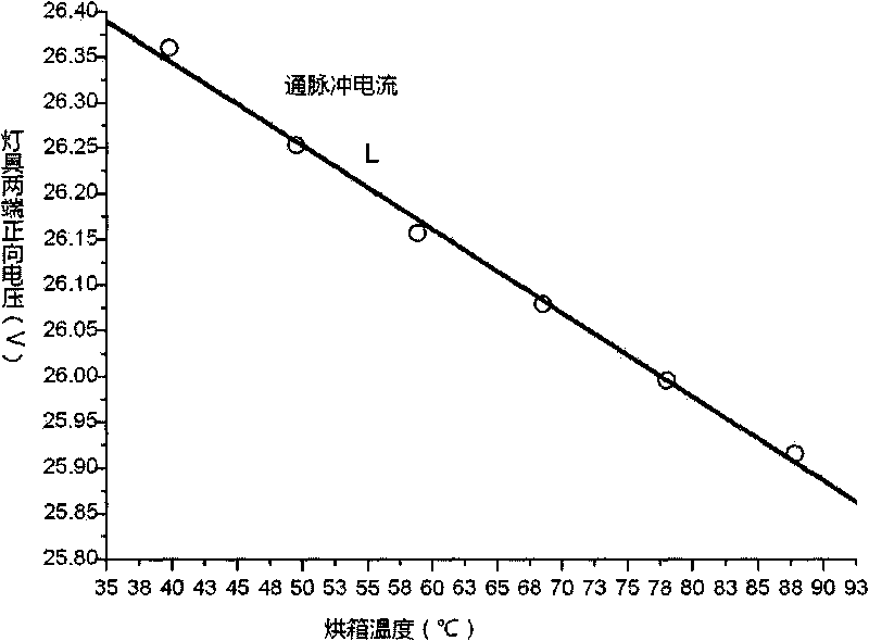
[0019] 3. Put the tested LED lamp in the oven, power on the inspection instrument, monitor and record the temperature in the oven through the inspection instrument. Turn on the pulse power supply to make the LED lamp emit pulse light. The pulse power supply provides continuous pulse current to the lamp. The size of the lamp’s DC working current is 2.8A, the width is 550μs, and the duty cycle of the pulse current is 0.055%;

[0020] 4. Under ...


PUM


Abstract

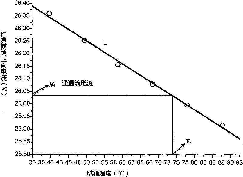
The invention discloses a method for detecting the junction temperature of a chip of an LED lamp, which comprises steps of: 1. under the electric current of extremely short pulse as the same as that that of the normal work of the lamp, obtaining the relationship between the positive voltage of the two ends of the lamp and the change of the junction temperature of the chip by controlling the temperature of ambient environment; 2. under the DC normal work of the lamp, obtaining the positive voltage of the two ends of the lamp when achieving the stability of the thermal balance; and 3. substituting the positive voltage data into the relationship obtained in step 1 between the positive voltage of the lamp and the junction temperature of the chip to ensure the work junction temperature of the chip of the lamp under normal working condition. The method can exactly judge the work junction temperature of the chip of the LED lamp under different working currents, and is good for the heat dispersion of the LED lamp, the evaluation of the service life and the optimization design of the lamp.

Description

technical field [0001] The invention relates to a detection method of a photoelectric element, in particular to a method for detection of chip junction temperature of an LED lamp. Background technique [0002] With the continuous improvement of the light efficiency and lifespan of high-power white LED chips, the application of high-power LED lighting fixtures based on multiple LED chips is becoming more and more extensive, such as car lights, street lights, and display backlights. Under the light effect of the current white LED, these high-power LED lamps will convert more than 70% of the input electric energy into heat while emitting light. If the heat accumulates too much and cannot be dissipated, it will cause the junction temperature of the LED lamp chip If it is too high, the light color parameters will degrade, the light efficiency will decrease, and the color temperature will drift, which will shorten the service life of LED lamps. Therefore, while using LED lamps fo...

Claims


Application Information

Patent Timeline
IPC IPC(8): G01K7/18
Inventor 陈亮刘石神张涛章美敏顾建忠童广辉何彬锋
Owner SHANGHAI INST OF TECHNICAL PHYSICS - CHINESE ACAD OF SCI
Learn More