Fiber grating monitoring system for power transmission line

A fiber grating and monitoring system technology, applied in the field of electric power, can solve the problems of transmission speed and image quality limitations, difficulty in guaranteeing the stability and service life of resistance strain gauges, and low measurement accuracy

Inactive Publication Date: 2010-05-05
NORTH CHINA ELECTRIC POWER UNIV (BAODING)
View PDF0 Cites 19 Cited by
  • Summary
  • Abstract
  • Description
  • Claims
  • Application Information

AI Technical Summary

Problems solved by technology

[0004] The method of real-time monitoring of sag through the combination of real-time monitoring of line images and small weather stations is greatly affected by weather conditions, and the measurement accuracy is very low, and the transmission speed and image quality are greatly limited; by measuring the stress and inclination angle of wire suspension fittings The method to calculate the sag is the traditional resistance strain gauge load cell. The method of measuring the tension on the fitting is to use the established mechanical model to calculate the wire sag, but the resistance strain gauge relies on the weak resistance change to reflect The strain of the component, there are factors such as nonlinearity, temperature, and zero position drift, and a precise bridge measurement circuit is required to ensure the accuracy of the measurement, and the strong alternating electromagnetic field of the transmission line on the transmission line will generate a relatively high voltage on the lead wire of the strain gauge. High induced voltage, small size of insulator fittings, difficult construction of bridge or circuit compensation, and difficulty in guaranteeing the stability and service life of resistance strain gauges under harsh conditions on site. These influencing factors cause large errors in test results; The method of measuring wire sag is based on the state equation to obtain the horizontal tension, and then the principle of calculating the sag by the horizontal tension is realized. Due to the difference in the temperature of the wire inside and outside, the error of the temperature measuring device will be enlarged in the state equation , which directly causes the inaccuracy of the measurement, and cannot measure the sag under load
Due to the low power supply, the existing system often adopts the sleep mode to save power. For example, the system is set to sleep for half an hour between two icing monitoring, so that real-time monitoring of the icing situation cannot be carried out.
Each measurement point (each measurement pole) needs to include a measurement module, a power-taking module and a wireless transmission module, resulting in a higher overall cost of the system
[0005] In the process of realizing the present invention, the inventor found that the online monitoring method in the prior art is on-site active measurement, which needs to provide power near the measurement point. Due to the influence of the environment, it cannot be used in continuous rainy weather, the power of the wire is small, and it is easy to be damaged when a short circuit fault occurs in the power system

Method used


Image

  • Fiber grating monitoring system for power transmission line
  • Fiber grating monitoring system for power transmission line
  • Fiber grating monitoring system for power transmission line

Examples


Embodiment Construction

[0018] The present invention will be described in detail below with reference to the accompanying drawings and in combination with embodiments.

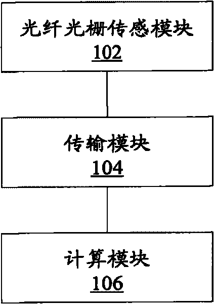
[0019] figure 1 A schematic diagram of a fiber grating monitoring system for power transmission lines according to an embodiment of the present invention is shown, including: a fiber grating sensing module 102, a transmission module 104 and a calculation module 106, wherein

[0020] The fiber grating sensing module 102 is configured to receive the first optical signal transmitted by the transmission module 104, and transmit the second optical signal reflected by the first optical signal to the calculation module 106 through the transmission module 104;

[0021] a transmission module 104, configured to transmit the first optical signal and the second optical signal;

[0022] The calculation module 106 is configured to obtain the tension and inclination angle borne by the transmission line according to the change of the center wavelen...


PUM


Abstract

The invention discloses a fiber grating monitoring system for a power transmission line, which comprises a fiber grating sensing module, a transmission module and a computation module, wherein the fiber grating sensing module is used for receiving a first optical signal transmitted from the transmission module, and transmitting a second optical signal after the reflection of the first optical signal to the computation module through the transmission module; the transmission module is used for transmitting the first optical signal and the second optical signal; and the computation module is used for acquiring the pulling force borne by the power transmission line and the inclination angle of the power transmission line according to the change of the center wavelength of the second optical signal relative to the first optical signal, and acquiring the ice cover of the power transmission line according to the pulling force and the inclination angle.

Description

technical field [0001] The invention relates to the field of electric power, in particular to an optical fiber grating monitoring system for power transmission lines. Background technique [0002] Electricity security is an important part of national security. Under the current background of rapid economic development in my country, the whole society has higher and higher requirements for power reliability, and the economic losses caused by power accidents are becoming more and more serious. Due to their wide distribution and harsh environment, transmission lines often encounter large-scale pollution flashovers, icing, and lightning strikes, and are weak links in the power grid. [0003] Electric power departments and research institutions at home and abroad have conducted research on online sag monitoring of transmission lines for many years. At present, there are mainly the following online sag monitoring methods: monitoring sag by image resolution measurement; measuring ...

Claims


Application Information

Patent Timeline
Patent Type & Authority Applications(China)
IPC IPC(8): G01L1/24G01B11/26
Inventor 马国明李成榕程养春
Owner NORTH CHINA ELECTRIC POWER UNIV (BAODING)
Why Eureka
Try Eureka