Annular whisker optical fiber stress monitoring device

A fiber optic stress and monitoring device technology, which is applied in the measurement of the change force of the optical properties of the material when it is stressed, can solve the problems of high false alarm frequency of the monitoring device, high use and maintenance costs, and low automatic discrimination technology , to achieve the effects of flexible use, low maintenance and use costs, and simple structure

Inactive Publication Date: 2010-11-10
XIAN JINHE OPTICAL TECH
View PDF5 Cites 3 Cited by
  • Summary
  • Abstract
  • Description
  • Claims
  • Application Information

AI Technical Summary

Problems solved by technology

The current software automatic discrimination technology of the camera video recognition system is not high, and it needs someone to be on duty.
[0003] And existing optical fiber perimeter alarm system mainly contains two kinds: 1, be that various structures come to the police by the change of the microbending loss of optical fiber, as " intrusion detection device " of U.S. Patent No. "Boundary Monitoring Method and System", and US Patent No. US6980108B1 "Intrusion Detection System Based on Optical Cable" and other patents are all monitored by the change of the microbend loss of the optical fiber, but the schemes proposed by these patents are complicated and expensive to use and maintain. 2. It is an optical fiber perimeter alarm system based on light interference technology. For example, the Chinese patent application number is 200710094598.5 "perimeter security monitoring system and method", and the Chinese patent application number is 200810116782.X "realization Optical fiber perimeter alarm method and device" and other patents are all based on the principle of light interference for monitoring. The advantage of light interference is that it is very sensitive. However, this is also the shortcoming of this type of monitoring device. It requires a variety of soft, However, due to the complexity of the actual environment, the false alarm frequency of this type of monitoring device is high, the operation is complicated, and the long-term stability is poor, which leads to the production, use and maintenance of this type of system. The cost is high and the effect is poor

Method used


Image

  • Annular whisker optical fiber stress monitoring device
  • Annular whisker optical fiber stress monitoring device
  • Annular whisker optical fiber stress monitoring device

Examples


Embodiment 1

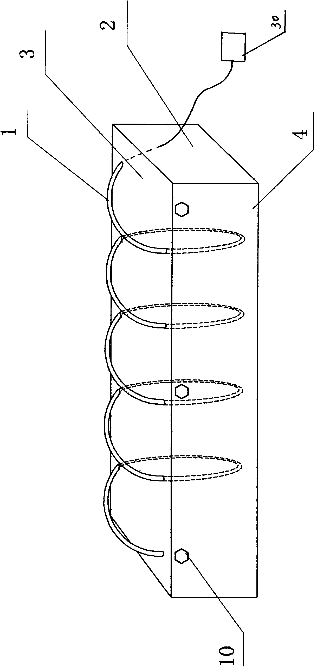
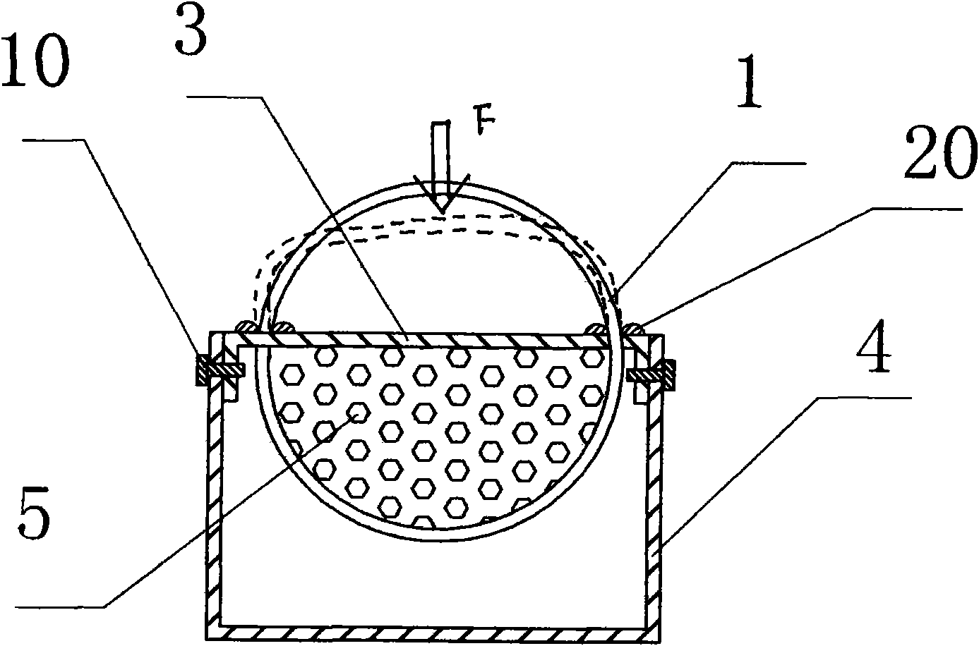
[0034] Such as figure 1 , figure 2 As shown, the present invention has a ring-shaped tentacles-shaped optical fiber stress monitoring device, which includes a plurality of ring-shaped structures composed of optical cables 1 and fixed on the top cover 3, and a part of the ring-shaped structures is contained in the base body 2 And there is an elastic material 5 between the top cover 3, and there is a bending limiter 20 at the joint between the optical cable 1 and the top cover 3. The top cover 3 and the U-shaped groove 4 are connected and fixed by screws 10 to form a base 2. One end of the optical cable 1 Connect with test unit 30.

[0035] In this embodiment, the annular structure formed by the optical cable 1 presents a helical shape as a whole. When stress acts on the optical cable 1, the bending curvature of the optical cable 1 changes and causes the power of the optical signal transmitted in the optical fiber of the optical cable 1 to change. Pass the test The unit 30 mo...

Embodiment 2

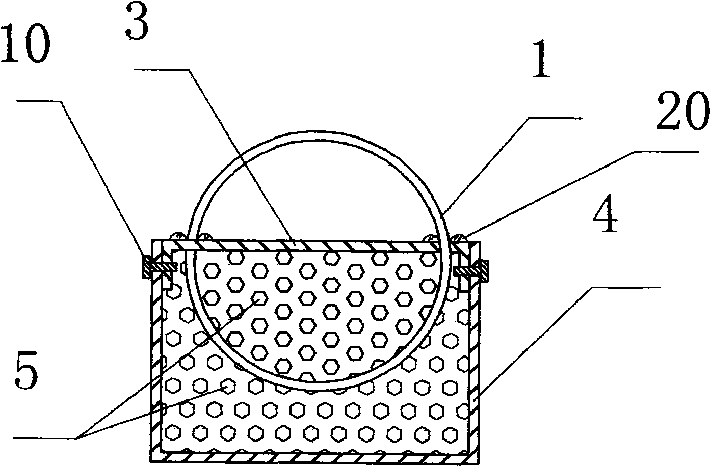
[0037] Such as image 3 As shown, in this embodiment, the difference from Embodiment 1 is that in the matrix 2 composed of the top cover 3 and the U-shaped groove 4, except that there is an elastic material between the male optical cable 1 and the top cover 3, there is a gap between the optical cable 1 and the U-shaped groove 4. There is also elastic material between the grooves 4, so as to ensure the fixed position of the optical cable 1 and prevent the optical cable 1 from moving in a wide range. In this embodiment, the structures, connections and working principles of other parts are the same as those in Embodiment 1.

Embodiment 3

[0039] Such as Figure 4 As shown, in this embodiment, the difference from Embodiment 1 is that the annular structure formed by the optical cable 1 is wavy, and a part of the wavy optical cable 1 is outside the base 2 , and the other part is inside the base 2 . In this embodiment, the structures, connections and working principles of other parts are the same as those in Embodiment 1.


PUM


Abstract

The invention discloses an annular whisker optical fiber stress monitoring device which comprises a plurality of annular structures composed of an optical cable, wherein a part of the annular structures is contained in a matrix; and at least one end of the optical cable is connected with a test unit. When a stress is applied to the annular whisker optical cable, the bending curvature of the optical cable is reduced so that the bending curvature of the optical fiber in the optical cable is also reduced to change the bend loss of the optical fiber. A stress signal is transformed into an optical signal and then transmitted to the test unit through the optical fiber, thus achieving the purpose of remote monitoring; and if the optical cable is changed into a pressure-sensitive optical cable, the monitoring sensitivity and the monitoring accuracy of the optical fiber stress monitoring device can be further improved. The annular whisker optical fiber stress monitoring device of the invention has the advantages of simple structure, rational design, convenient processing and manufacturing, flexible usage mode, high sensitivity and good use effect; and testing instruments such as an optical time domain reflectometer and the like can achieve distributed stress monitoring.

Description

technical field [0001] The invention relates to a stress monitoring device, in particular to a ring-shaped tentacles-shaped optical fiber stress monitoring device, which is an optical fiber sensing device suitable for perimeter monitoring. Background technique [0002] At present, the security systems applied to perimeter alarm mainly include: microwave alarm system, active infrared alarm system, leaking cable perimeter alarm system, static induction perimeter alarm system, camera video recognition system, fiber optic perimeter alarm system, etc. But the above-mentioned traditional perimeter alarm system has many problems in application. For example, monitoring methods such as microwave alarm system or active infrared alarm system can only be used in line-of-sight and flat areas, and are greatly affected by environmental factors such as terrain heights, twists and turns, turns, and bends. Influenced by climate, the accuracy rate is also lower. The life of the sensor unit i...

Claims


Application Information

Patent Timeline
Patent Type & Authority Applications(China)
IPC IPC(8): G01L1/24
Inventor 杜兵杜蔚杜迎涛
Owner XIAN JINHE OPTICAL TECH
Why Eureka
Try Eureka