Redox flow cell stack

A liquid flow battery stack and liquid flow frame technology, applied in the field of battery stack structure, can solve problems such as inaccurate positioning, misalignment between components, corrosion of current collector inlet and outlet, and achieve electrolyte leakage prevention and tightness Good, easy to assemble

Active Publication Date: 2010-05-05
大力储能技术湖北有限责任公司
View PDF4 Cites 8 Cited by
  • Summary
  • Abstract
  • Description
  • Claims
  • Application Information

AI Technical Summary

Problems solved by technology

[0003] Existing liquid flow batteries, such as those disclosed in Chinese applications 200710105754.3, 200810030801.7, 200510086917.9, and 200610011470.3, all have holes on the current collector for the electrolyte to enter and exit. When flowing in the stack, it is easy to cause corrosion of the inlet and ou...

Method used


Image

  • Redox flow cell stack
  • Redox flow cell stack
  • Redox flow cell stack

Examples


Embodiment Construction

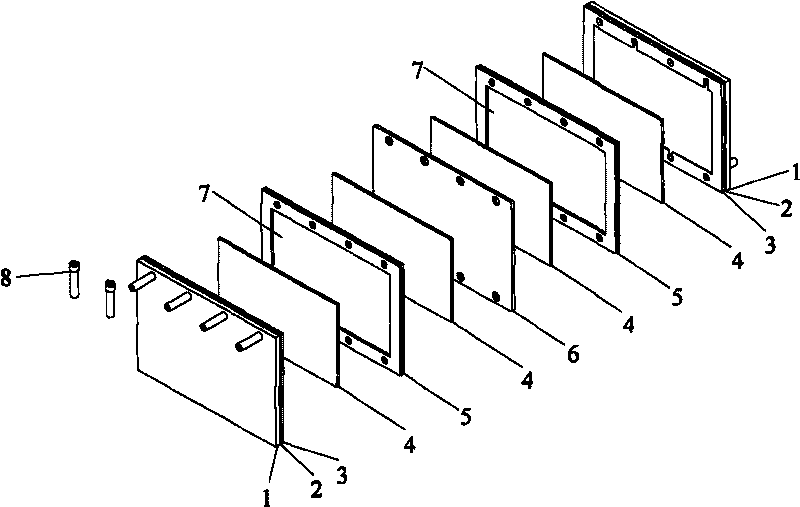
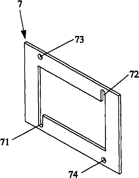
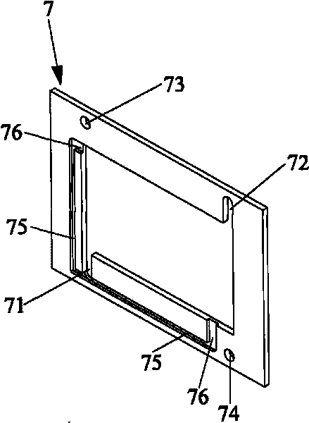
[0019] In a first embodiment of the invention, see figure 2 , The liquid flow frame 7 is a rectangular frame, and the liquid flow frame is provided with a liquid inlet hole 71 and a liquid outlet hole 72, which are respectively used to guide the electrolyte to the surface of the current collector 3 and lead it out. In addition, the liquid flow frame 7 is provided with perforations 73 and 74 as flow channels for the battery stack electrolyte to flow to other battery units.

[0020] In this embodiment, the current collector 3 is approximately equal in size to the liquid flow frame 7. When the battery stack is assembled, the current collector 3 is pressed against one side of the liquid flow frame 7, so that the liquid inlet hole 71 can guide the electrolyte To the surface of the current collector, the liquid outlet hole 72 can lead the electrolyte from the surface of the current collector.

[0021] As a preference, the liquid flow frame 7 can be set in a concave structure, that...


PUM


Abstract

The invention provides a redox flow cell stack which comprises at least two redox flow frames (7) and flow collecting bodies (3) with the number corresponding to that of the redox flow frames. The redox flow cell stack is characterized in that the redox flow frames are provided with a liquid inlet hole (71) and a liquid outlet hole (72) which are respectively used for leading electrolyte onto the surface of the flow collecting bodies and out of the surface thereof. The design of the invention can avoid the phenomena of seepage and weeping since the liquid inlet hole and the liquid outlet hole of the flow collecting bodies (3) are scoured by the electrolyte in the flowing process; meanwhile, the liquid inlet hole, the liquid outlet hole and flow channels can be conveniently designed on the redox flow frames, so that the liquid flow inside a cell can be more balanced and smooth.

Description

technical field [0001] The invention relates to the field of fuel cells, in particular to a battery stack structure of a vanadium battery. Background technique [0002] The battery stack of a flow battery (such as a vanadium redox flow battery) is usually composed of a certain number of single cells connected in series. Each single cell is composed of a current collector (single collector plate), a liquid flow frame, an electrode, a diaphragm, an electrode, a liquid flow frame, and a current collector (single collector plate). figure 1 It shows a diagram of the components of a battery stack composed of two single cells, starting from the liquid inlet according to the end plate 1, the gasket 2, the current collector (unipolar plate) 3, the electrode 4, the liquid flow frame 5, and the diaphragm 7 , electrode 4, bipolar plate (collector) 6, electrode 4, liquid flow frame 5, electrode 4, current collector (unipolar plate) 3, gasket 2, and end plate 1 are assembled into a batte...

Claims


Application Information

Patent Timeline
IPC IPC(8): H01M8/18H01M8/24H01M10/36H01M8/04H01M2/02H01M2/10H01M8/0258H01M8/2465
CPCY02E60/12Y02E60/528Y02E60/50Y02E60/10
Inventor 史小虎刘素琴张庆华黄可龙周萱王海华李虹云刘维维刘根深王欢许秀惠
Owner 大力储能技术湖北有限责任公司
Why Eureka
Try Eureka