
Bandwidth compensating device of channel of digital oscilloscope
A digital oscilloscope and compensation device technology, applied in the direction of digital variable display, etc., can solve problems such as relationship deterioration and achieve the effect of increasing bandwidth
- Summary
- Abstract
- Description
- Claims
- Application Information
AI Technical Summary
Problems solved by technology
Method used
Image

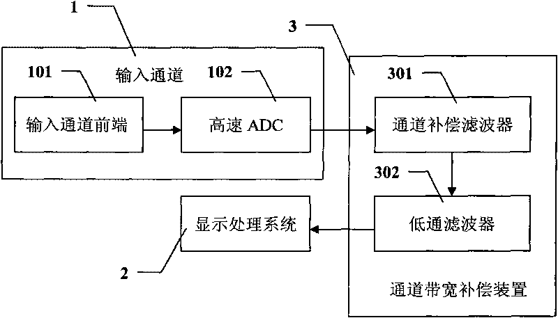

Examples
Embodiment
[0035] 1. Acquisition of the frequency response amplitude-frequency characteristics of the input channel
[0036] In the specific implementation process, it is first necessary to obtain the frequency response amplitude-frequency characteristics of the input channel, usually the following two methods can be used:
[0037] 1), sine sweep
[0038] Perform sinusoidal excitation on the input channel, keep the amplitude of the excitation force constant, change the excitation frequency according to a certain rule, and pick up the vibration response of the input channel, so as to obtain the frequency response amplitude-frequency curve of the input channel.
[0039] 2), pulse excitation
[0040] The input channel is excited by the pulse signal, and the input and output of the input channel are Fourier transformed, and the frequency response amplitude-frequency curve can be calculated.
[0041] Use the pulse excitation method to obtain the system channel frequency response:
[0042] ...
PUM
 Abstract
Description
Claims
Application Information