

Method for detecting arc faults based on time-frequency characteristics of high-frequency current component
An arc fault, high-frequency component technology, applied in voltage/current isolation, measurement using digital measurement technology, spectrum analysis/Fourier analysis, etc. The effect of strong interference ability, reduction of misoperation rate, and wide linearity range
- Summary
- Abstract
- Description
- Claims
- Application Information
AI Technical Summary
Problems solved by technology
Method used
Image

Examples
Embodiment Construction
[0025] specific implementation plan
[0026] The present invention will be described in further detail below in conjunction with the accompanying drawings.
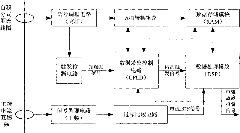
[0027] see figure 1 , The overall structure of the system hardware of the present invention includes a self-integrating Rogowski coil, a signal conditioning circuit (high frequency), an A / D conversion circuit, a trigger detection circuit, a power frequency current transformer, a signal conditioning circuit (power frequency), and a zero-crossing comparison circuit , data acquisition control circuit, data storage module and data processing module.
[0028] The high-frequency signal output by the Rogowski coil is processed by the signal conditioning circuit (high frequency) and the trigger detection circuit to generate a pre-trigger signal, which is sent to the data acquisition control circuit to start the high-frequency signal acquisition; in the control of the data acquisition control module Next, the conditioned signal is...
PUM
 Abstract
Description
Claims
Application Information