Fly-by-wire device for trainer aircraft

A technology of fly-by-wire control and trainer aircraft, which is applied in the field of aircraft flight control system, can solve the problems of complex mechanical interface between the front cabin control stick and pedals, unfavorable cockpit sealing, and inability to realize aircraft maneuverability flight, etc., and achieve the requirements of simplicity, The effect of improving training efficiency

Active Publication Date: 2010-05-12
JIANGXI HONGDU AVIATION IND GRP
View PDF0 Cites 14 Cited by
  • Summary
  • Abstract
  • Description
  • Claims
  • Application Information

AI Technical Summary

Problems solved by technology

[0002] The mechanical linkage between the front and rear cabin cockpit and pedals is the most effective way to effectively realize aircraft piloting training. The existing fly-by-wire control devices for trainer pilots only realize the mechanical linkage of the front and rear cabins for partial direction control, and the linkage lever system It directly passes through the middle passage, occupying the middle passage of the cockpit, and is easy to be stuck by falling foreign objects, which affects the safety of the aircraft. All accessories are arranged in a centralized manner and installed in the front cabin, hinged with the cockpit, so that the overall space is larger , sometimes placing an additional weight burden on the aircraft
This type of pilot control device has the following deficiencies: 1) During pilot training, the unlinked direction of the front and rear cabin controls is generally allocated to the control authority of the front and rear cabin pilots in a certain pro

Method used


Image

  • Fly-by-wire device for trainer aircraft
  • Fly-by-wire device for trainer aircraft
  • Fly-by-wire device for trainer aircraft

Examples


Embodiment

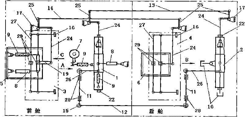
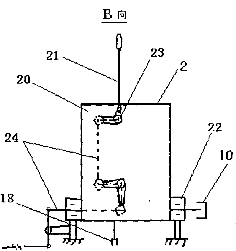
[0023] A fly-by-wire control device for a trainer, which consists of a front cabin control rod assembly 1, a rear cabin control rod assembly 2, a front cabin pedal mechanism 3, a rear cabin pedal mechanism 4, a longitudinal linkage rod 12, a transverse linkage rod 13, and a heading linkage A rod 14, a displacement sensor 8, a load mechanism 9, an eddy current damper 10 and a longitudinal adjustment mechanism 7 form a longitudinal control system, a lateral control system and a heading control system:

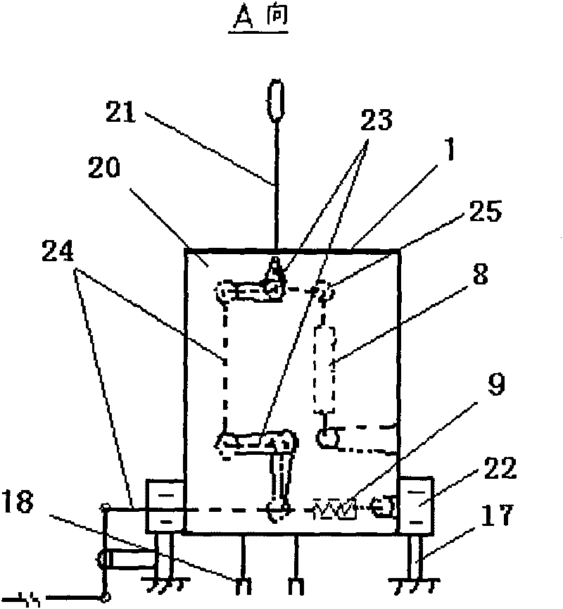
[0024]The longitudinal control system consists of front and rear cabin control rod assemblies (YKH-10A, YKH-11A) 1, 2, displacement sensor (2588A) 8, longitudinal adjustment mechanism (DG-195) 7, eddy current damper (ZNQ-1Z ) 10, the load mechanism 9 and the longitudinal linkage rod 12 for front and rear cabin linkage. The displacement sensor 8 is installed behind the front cabin steering column assembly 1 and is hinged with the arm 18 on the steering column rotary box 20. The lon...


PUM


Abstract

The invention relates to a fly-by-wire device for a trainer aircraft, which is characterized in that: a longitudinal linkage rod, a transverse linkage rod and a course linkage rod passes through two sides of each of front and back cockpits; and a displacement sensor, an eddy-current damper and an adjustment mechanism are arranged on the front and back cockpits respectively. The device has the advantages that: 1) the mechanism linkage is realized in both the front and back cockpits operated by a longitudinal axis, a transverse axis and a course axis, so the mechanical and electrical properties of the front and back cockpits are completely consistent, which contributes to the improvement of training efficiency and the safe operation of the aircraft; 2) the operating rod systems of the front and back cockpits are changed by a few driving rod systems to pass through from two sides of a control console, so the simple layout requirements of the cockpits are met; and 3) the driving displacement sensor, the eddy-current damper, the adjustment mechanism and the like are distributed in the front and back cockpits on the premise of ensuring the important operating properties of the systems, so the whole driver operation device can make a flexible and high-efficiency use of the space of the front and back cockpits in the front and back cockpits.

Description

technical field [0001] The invention relates to an aircraft flight control system, in particular to a fly-by-wire control device for a trainer. Background technique [0002] The mechanical linkage between the front and rear cabin cockpit and pedals is the most effective way to effectively realize aircraft piloting training. The existing fly-by-wire control devices for trainer pilots only realize the mechanical linkage of the front and rear cabins for partial direction control, and the linkage lever system It directly passes through the middle passage, occupying the middle passage of the cockpit, and is easy to be stuck by falling foreign objects, which affects the safety of the aircraft. All accessories are arranged in a centralized manner and installed in the front cabin, hinged with the cockpit, so that the overall space is larger , sometimes bringing an additional weight burden to the aircraft. This type of pilot control device has the following deficiencies: 1) During p...

Claims


Application Information

Patent Timeline
IPC IPC(8): G09B19/16
Inventor 梁琼花郑志伟崔彦勇周继强叶蕾
Owner JIANGXI HONGDU AVIATION IND GRP
Why Eureka
Try Eureka